How to Convert a Basic Wiring Diagram to a PLC Program
✅ C'mon over to https://realpars.com where you can learn PLC programming faster and easier than you ever thought possible!
=============================
✅ Check out the full blog post over at
https://realpars.com/wiring-diagram-to-plc-program/
=============================
In this video, you will learn how to convert a basic wiring diagram to a ladder logic PLC program. This can be a very handy skill to learn, especially if you are converting a machine to PLC control.
Upgrading a machine to PLC control may seem like a daunting task. However, if you take your time and learn the basics, it can be an easily achievable task.
I will walk you through programming a very basic “stop-start” circuit for an electric motor. This should help you get a handle on some of the basics.
First, let’s look at our basic start and stop diagram. I like to start on the left and follow the line. Each line represents a wire that is connected.
L1 is our 120v hot wire. It will run straight to the normally closed Stop button labeled PB1.
From the other terminal on PB1, it runs to a normally open PB2 which is our Start button. From the other terminal on PB2, a wire connects to the A1 terminal on the Motor Starter Coil.
The A2 terminal runs to the normally closed overload auxiliary contact. The next wire runs from the other overload terminal to neutral.
The next line down shows how a motor starter stays energized. One wire needs to be connected to the input terminal of the start push button.
It will run to one terminal of the auxiliary contact set on the motor starter. This ensures power is on the auxiliary contact.
The second terminal of the auxiliary contact is connected to the output side of the start push button.
When the start button is pushed, the circuit is complete and the motor starter will energize. This closes the auxiliary contact and allows the operator to release the start button.
The motor starter will now stay energized until the stop button is pressed and the circuit opens.
Programming software is all different but similar. Most have a toolbox somewhere that you will drag your contacts and coils from.
Just like on the diagram, we start with the stop pushbutton. It will be represented with an examine OFF bit. These look like a normally closed contact.
Drag it to the first ladder rung and the program will place it to the far left. This will be a stop push button.
Next, drag an examine ON bit and drop it to the right of the first bit. This looks like normally open contact and will be the start push button.
And continue to complete your PLC programming logic according to this simple start-stop wiring diagram.
To wrap it up, to program a simple motor start-stop circuit, we need to read the electrical diagram from left to right and open our toolbox on the programming software.
You will be using the most common bits in the examine ON, examine OFF, and output coil or output energize.
Again, the language is sometimes different between manufacturers, but the symbols pretty well look the same.
The bits will represent normally open and normally closed inputs, and a single output. You will also need to use a branch around one bit. This is basically a parallel circuit and OR logic.
The start push button OR the auxiliary contact will energize the circuit.
I hope this video has been helpful in the transition from wiring diagrams to plc programming. This was a very basic program that can run a motor.
=============================
Missed our most recent videos? Watch them here:
https://realpars.com/ethercat
https://realpars.com/encoder
https://realpars.com/ethernet-ip
=============================
To stay up to date with our last videos and more lessons, make sure to subscribe to this YouTube channel:
http://goo.gl/Y6DRiN
=============================
TWEET THIS VIDEO https://ctt.ac/a3Ykh
=============================
Like us on Facebook: https://www.facebook.com/therealpars/
Follow us on Twitter: https://twitter.com/realpars
Follow us on LinkedIn https://www.linkedin.com/company/realpars
#RealPars #ElectricalWiringDiagram #PLC
Видео How to Convert a Basic Wiring Diagram to a PLC Program канала RealPars
=============================
✅ Check out the full blog post over at
https://realpars.com/wiring-diagram-to-plc-program/
=============================
In this video, you will learn how to convert a basic wiring diagram to a ladder logic PLC program. This can be a very handy skill to learn, especially if you are converting a machine to PLC control.
Upgrading a machine to PLC control may seem like a daunting task. However, if you take your time and learn the basics, it can be an easily achievable task.
I will walk you through programming a very basic “stop-start” circuit for an electric motor. This should help you get a handle on some of the basics.
First, let’s look at our basic start and stop diagram. I like to start on the left and follow the line. Each line represents a wire that is connected.
L1 is our 120v hot wire. It will run straight to the normally closed Stop button labeled PB1.
From the other terminal on PB1, it runs to a normally open PB2 which is our Start button. From the other terminal on PB2, a wire connects to the A1 terminal on the Motor Starter Coil.
The A2 terminal runs to the normally closed overload auxiliary contact. The next wire runs from the other overload terminal to neutral.
The next line down shows how a motor starter stays energized. One wire needs to be connected to the input terminal of the start push button.
It will run to one terminal of the auxiliary contact set on the motor starter. This ensures power is on the auxiliary contact.
The second terminal of the auxiliary contact is connected to the output side of the start push button.
When the start button is pushed, the circuit is complete and the motor starter will energize. This closes the auxiliary contact and allows the operator to release the start button.
The motor starter will now stay energized until the stop button is pressed and the circuit opens.
Programming software is all different but similar. Most have a toolbox somewhere that you will drag your contacts and coils from.
Just like on the diagram, we start with the stop pushbutton. It will be represented with an examine OFF bit. These look like a normally closed contact.
Drag it to the first ladder rung and the program will place it to the far left. This will be a stop push button.
Next, drag an examine ON bit and drop it to the right of the first bit. This looks like normally open contact and will be the start push button.
And continue to complete your PLC programming logic according to this simple start-stop wiring diagram.
To wrap it up, to program a simple motor start-stop circuit, we need to read the electrical diagram from left to right and open our toolbox on the programming software.
You will be using the most common bits in the examine ON, examine OFF, and output coil or output energize.
Again, the language is sometimes different between manufacturers, but the symbols pretty well look the same.
The bits will represent normally open and normally closed inputs, and a single output. You will also need to use a branch around one bit. This is basically a parallel circuit and OR logic.
The start push button OR the auxiliary contact will energize the circuit.
I hope this video has been helpful in the transition from wiring diagrams to plc programming. This was a very basic program that can run a motor.
=============================
Missed our most recent videos? Watch them here:
https://realpars.com/ethercat
https://realpars.com/encoder
https://realpars.com/ethernet-ip
=============================
To stay up to date with our last videos and more lessons, make sure to subscribe to this YouTube channel:
http://goo.gl/Y6DRiN
=============================
TWEET THIS VIDEO https://ctt.ac/a3Ykh
=============================
Like us on Facebook: https://www.facebook.com/therealpars/
Follow us on Twitter: https://twitter.com/realpars
Follow us on LinkedIn https://www.linkedin.com/company/realpars
#RealPars #ElectricalWiringDiagram #PLC
Видео How to Convert a Basic Wiring Diagram to a PLC Program канала RealPars
Показать
Комментарии отсутствуют
Информация о видео
Другие видео канала
 How to Draw a Wiring Diagram and Turn it into a PLC Program (EPLAN Tutorial) Reverse Forward Starter
 What is Ladder Logic?
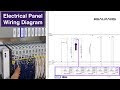 PLC Wiring Diagram - How to EASILY read it
 What are the Differences between DCS and SCADA?
 How to Wire Discrete DC Sensors to PLC - Part 1
 What is a Servo Motor and How it Works?
 What are the Most Popular PLC Programming Languages?
 Photoelectric Sensor Wiring and Setup
 PLC Programming Tutorial for Beginners_ Part 1
 Ladder Logic Documentation (Full Lecture)
 What are the differences between SIMATIC S7-300 and S7-1500 PLCs?
 PLC Analog Inputs and Signals
 LD 11 - Motors Start with Interlock - Easy PLC Programming Tutorials for Beginners
 Bottle Filling Process PLC Program _ Part 1
 Siemens S7-1500: First Time Wiring and Programming
 Siemens PLC Training: How to Write PLC Ladder Program | PLC Program for Water Tank Level Control
 What is Modbus and How does it Work?
 How to Read Electrical Diagrams | Wiring Diagrams Explained | Control Panel Wiring Diagram
 Programable Logic Controller Basics Explained - automation engineering