PLC Wiring Diagram - How to EASILY read it
▶ C'mon over to https://realpars.com where you can learn PLC programming faster and easier than you ever thought possible!
=============================
▶ Check out the full blog post over at
https://realpars.com/panel-wiring-diagram/
=============================
In this video, we’re going to go back and have a look at the control panel, and try and figure out some of the connections by following a wiring diagram.
As we’ve said before, this is a control panel that is used for a system that turns wastewater into clean water.
It is a 2-door control panel on the front of which we have some switches that are connected to the PLC inputs and outputs.
We are going to look at these switches and try and figure out the wiring behind them, as you may be curious as to how these switches are wired to the PLC!
Let us first identify our push buttons; we have the Mute Buzzer push button, the ESD Reset push button and the Emergency Stop push button.
Try to remember them, and see if we can find any of these items in the electrical drawings.
All the wiring that you see in the panel is done based on the wiring diagram. This is what we draw using AutoCAD.
Each page of this wiring diagram shows the exact wiring for different sections of this control panel.
In the back of the Emergency Stop push button, you see that we have four wires, just as what we have on the wiring diagram.
Two wires are tagged as 1 and two wires are tagged as 2. Based on the diagram, one of these wires with the tag 2 goes to the PLC digital input.
It says the tag for the PLC input that the push button is connected to is 300U2.1.
These are the tags for the PLC inputs and outputs.
One end of this diagram is connected to the push button and the other end is connected to the PLC input. So this is how easy it is to read the wiring diagram for a control panel.
It goes exactly the same for the other switches that we have here as well.
So to sum it all up, here is what you are going to learn after watching this video:
– All the wiring that you see in the panel is done based on the wiring diagram. This is what we draw using AutoCAD Electrical.
– Each page of the wiring diagram shows the exact wiring for different sections of the control panel.
– Each of the wires in the wiring diagram has a tag number. These tags can be found in the panel as well.
– Using the page numbers and the sections, in the wiring diagram, you can easily follow the wires and see where each wire is coming from.
=============================
If you want to get in contact with Pro-control, you can check out their website over at https://www.pro-control.nl/
=============================
Missed our most recent videos? Watch them here:
https://realpars.com/main-switch/
https://realpars.com/orange-wire-control-panel/
https://realpars.com/electrical-control-panel-basics/
=============================
To stay up to date with our last videos and more lessons, make sure to subscribe to this YouTube channel:
http://goo.gl/Y6DRiN
=============================
TWEET THIS VIDEO https://ctt.ac/1X_41
=============================
Like us on Facebook: https://www.facebook.com/therealpars/
Follow us on Twitter: https://twitter.com/realpars
Follow us on LinkedIn https://www.linkedin.com/company/realpars
Follow us on Instagram https://www.instagram.com/realparsdotcom/
#RealPars #Automation #wiringdiagram
Видео PLC Wiring Diagram - How to EASILY read it канала RealPars
=============================
▶ Check out the full blog post over at
https://realpars.com/panel-wiring-diagram/
=============================
In this video, we’re going to go back and have a look at the control panel, and try and figure out some of the connections by following a wiring diagram.
As we’ve said before, this is a control panel that is used for a system that turns wastewater into clean water.
It is a 2-door control panel on the front of which we have some switches that are connected to the PLC inputs and outputs.
We are going to look at these switches and try and figure out the wiring behind them, as you may be curious as to how these switches are wired to the PLC!
Let us first identify our push buttons; we have the Mute Buzzer push button, the ESD Reset push button and the Emergency Stop push button.
Try to remember them, and see if we can find any of these items in the electrical drawings.
All the wiring that you see in the panel is done based on the wiring diagram. This is what we draw using AutoCAD.
Each page of this wiring diagram shows the exact wiring for different sections of this control panel.
In the back of the Emergency Stop push button, you see that we have four wires, just as what we have on the wiring diagram.
Two wires are tagged as 1 and two wires are tagged as 2. Based on the diagram, one of these wires with the tag 2 goes to the PLC digital input.
It says the tag for the PLC input that the push button is connected to is 300U2.1.
These are the tags for the PLC inputs and outputs.
One end of this diagram is connected to the push button and the other end is connected to the PLC input. So this is how easy it is to read the wiring diagram for a control panel.
It goes exactly the same for the other switches that we have here as well.
So to sum it all up, here is what you are going to learn after watching this video:
– All the wiring that you see in the panel is done based on the wiring diagram. This is what we draw using AutoCAD Electrical.
– Each page of the wiring diagram shows the exact wiring for different sections of the control panel.
– Each of the wires in the wiring diagram has a tag number. These tags can be found in the panel as well.
– Using the page numbers and the sections, in the wiring diagram, you can easily follow the wires and see where each wire is coming from.
=============================
If you want to get in contact with Pro-control, you can check out their website over at https://www.pro-control.nl/
=============================
Missed our most recent videos? Watch them here:
https://realpars.com/main-switch/
https://realpars.com/orange-wire-control-panel/
https://realpars.com/electrical-control-panel-basics/
=============================
To stay up to date with our last videos and more lessons, make sure to subscribe to this YouTube channel:
http://goo.gl/Y6DRiN
=============================
TWEET THIS VIDEO https://ctt.ac/1X_41
=============================
Like us on Facebook: https://www.facebook.com/therealpars/
Follow us on Twitter: https://twitter.com/realpars
Follow us on LinkedIn https://www.linkedin.com/company/realpars
Follow us on Instagram https://www.instagram.com/realparsdotcom/
#RealPars #Automation #wiringdiagram
Видео PLC Wiring Diagram - How to EASILY read it канала RealPars
Показать
Комментарии отсутствуют
Информация о видео
Другие видео канала
 Reviewing the Basics of an Electrical Control Panel (Practical Example)
 Crash Course on How to Read Electrical Schematics
 Control box assembly #3
 What is the Difference between VFD and Soft Starter?
 How to Tune a PID Controller
 A beginners guide to relays, contactors, and solenoids to automate anything; (#083)
 How to Wire Discrete DC Sensors to PLC - Part 2
 How to Read PLC Wiring Diagram | PLC Wiring Tutorial for Beginners | PLC Panel Wiring Diagram
 PLCnext - Connecting Industrial Automation to the IT World
 How To Read, Understand, And Use A Wiring Diagram - Part 1 - The Basics
 How to Read AC Wiring Diagram
 What is the Difference Between PLC and DCS?
 Variable Frequency Drives Explained - VFD Basics IGBT inverter
 Siemens S7-1500: First Time Wiring and Programming
 What Does an Orange Wire Do in an Electrical Control Panel?
 Control Panel Testing - Tips and Tricks
 How to Read Electrical Diagrams | Wiring Diagrams Explained | Control Panel Wiring Diagram
 How to Read a P&ID? (Piping & Instrumentation Diagram)
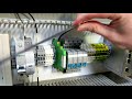 Control Panel Build Series Part 17: Wiring Power Distribution