1964 Philco AM tube clock radio
Here's a video of the repair of a tube-type 1964 Philco clock radio. It was necessary to replace the electrolytic capacitors in the power supply to eliminate the loud background hum and I also replaced the "across the AC line" capacitor as a safety precaution.
When replacing electrolytic capacitors, it is very important to observe polarity. If you get the negative and positive leads reversed, the capacitor could explode and you could cause injury to yourself as well as further injury to the radio. Typically, the radio will use a multi-section capacitor that will contain at least two capacitors in a single package. On the outside of the case, there will be markings to indicate the capacitor value in microfarads (uf, mf, mfd), the working voltage will be given (V, WV), and there will be some indication beside each value to indicate which terminal or lead matches the particular value.
There are very few multi-section capacitors being made today; so, we usually use common individual capacitors to make up the original multi-section capacitor. It will be necessary to connect the negative leads of the new capacitors together and these leads are indicated by a band with an arrow inside the band to indicate the negative lead.
When replacing a capacitor, the value of the new capacitor can be slightly higher or lower than the original capacitor. If you are replacing a 50uf cap, it is perfectly to use the now more common 47uf cap. The same goes for using a 33uf cap to replace a 30uf cap.
The working voltage of the new cap should be equal to, or greater than, the WV of the old capacitor. Never use a new cap with a lower WV rating than the original cap.
Most of the same rules apply when replacing a non-electrolytic cap. The only difference is that non-electrolytic caps are not polarity sensitive and it makes no difference which way the new cap is installed. Most caps found in vintage electronics that are below 1 uf will be of the non-electrolytic type. Anything 1uf or greater will usually be an electrolytic cap and polarity should be observed.
You'll need the standard assortment of tools (various screwdrivers, nutdrivers, pliers, wire cutters, wire strippers, etc). You'll also need at least a 60W soldering iron, some rosin core electronics solder, desoldering braid, and a handheld vacuum pump desoldering tool. I would have showed footage of the actual desoldering/soldering operation; but, I had no help with the camera and it would have been difficult to do it one handed.
One final note of caution: Many of these radios have one side of the AC line connected to the chassis, either directly through the chassis or through a capacitor and/or a resistor. Depending on the position of the plug in the AC outlet, there is a 50/50 chance that the "hot" side of the AC line will be connected to the chassis. In this case, if you touch the chassis while part of your body is in contact with something that has a return path to ground, you will receive a serious shock and you could be electrocuted. It's best to power up such radios through a line isolation transformer when powering up an exposed chassis.
Видео 1964 Philco AM tube clock radio канала radiotvphononut
Показать
Комментарии отсутствуют
Информация о видео
Другие видео канала
 1966 Philco-Ford all transistor AM/FM table radio
 Repair of a 1965 GE AM/FM tube clock radio
 Let George Do It - Travis Bell - 45 RPM
 Bandscan on a 1948 Crosley tube radio
 Lady Madonna - The Chords (?) - 26 Top Hits LP on Hit Records, 1968
 Repair of a 1966 talking book record player for the blind
 1984 Philco 12" B&W TV
 Spoken word 33 1/3 rpm record entitled, "Getting Acquainted With Sears"
 Repair of a late '40's PAL 78 rpm record player
 Early '60's Philco transistor radio
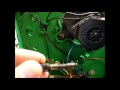 A79 talking book record player
 Santa Ana Winds - Ray Frushay - 45 RPM.wmv
 Zenith Royal 50 AM pocket transistor radio
 Lesley Duncan - Exactly Who You Are - 45 RPM.wmv
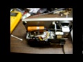 Repair of a 1965 model year Zenith all transistor AM table radio
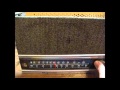 Repair of a 1967 Magnavox AM/FM radio
 Zero model 1265R single speed oscillating fan from the '60's
 Family Reunion - Travis Bell - 45 RPM.wmv
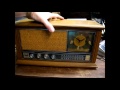 GE AM/FM solid state clock radio from 1968
 Church Bells May Ring - The Rockets (Prom Records)