Mercedes-Benz Axor - Mechanical valve clearance adjustment
Truck engines are not equipped with hydraulic valve clearance compensation like passenger cars.
The valve clearance is the small gap between the camshaft and valve.
This gap is necessary because the valve warms up and becomes longer during operation.
If this gap is too small, the following problems can occur:
The valve knocks against the camshaft, no longer closes correctly or even burns.
The clearance must therefore be regularly checked and adjusted if necessary.
There are several test methods for this.
Method 2, mechanical valve clearance adjustment, is shown here.
It is shown on engine model series 400, on inline engine 457.9.
The vehicle must remain idle for at least 30 minutes before the test is started.
This ensures that the engine temperature is uniform and prevents measurement errors.
Note: This time period still applies even if the vehicle is driven just a few meters into the workshop.
Tilt the cab forwards.
Remove the soundproofing cover.
This allows the cylinder head covers to be accessed more easily later.
Remove the two bolts on the cylinder head covers.
The order is unimportant.
Here, we start at cylinder 6.
Also remove the other five covers.
You now have an unobstructed view of the intake and exhaust valves.
A four-stroke engine is installed in the Axor.
This means that the valve clearance has to be checked and adjusted in two crankshaft positions.
The engine has to be set to the 'top dead center' position using a turning device.
This means that the piston is at the highest point in the cylinder.
First remove the two bolts on the cover of the inspection hole.
Screw the turning device to the inspection hole in the timing case.
Then crank the engine.
Note: Use a half-inch socket with a diameter of 10 mm.
Put it on the turning device upside down.
Use a ratchet with a size 10 hexagon socket bit.
The improved lever effect makes cranking easier.
Set the engine to the 'top dead center' crankshaft position.
Crank the engine until the TDC marking appears in the inspection hole.
A four-stroke engine has two different 'top dead center' positions.
For this reason, check which cylinder is at the TDC of the piston i.e. at ignition TDC.
Cylinder 1 is checked here - the rocker arms are free.
The first cylinder is thus at ignition TDC.
We are using the mechanical adjustment method here.
Next adjust the valve clearance of the cylinders with a feeler gauge.
Use the work instructions from WIS.
Start with cylinder 1.
Since the cylinder is at ignition TDC, both the exhaust and intake valves can be checked.
Coat the feeler gauge with oil to prevent any contact friction.
Check the valve clearance on the exhaust valve with a 0.6 mm thick feeler gauge.
Check the intake valve with a 0.4 mm thick feeler gauge.
It should be possible to pull the feeler gauge through on both valves with slight resistance.
This is not possible here.
The valve clearance is thus too small and must be readjusted.
Loosen the jam nuts.
First adjust the exhaust valve.
Adjust the clearance with the adjustment screw.
It must be possible to pull the blade of the feeler gauge between the rocker arm and valve with slight resistance.
Counterhold adjustment screw and tighten jam nut.
Use a 17 mm open-end wrench for this.
Tighten the jam nut to 50 Nm.
Check the clearance again as a precaution.
The adjustment screw could have turned when the jam nut was tightened.
The clearance would then be incorrectly adjusted once again.
Correct the clearance on the intake valve in the same way.
Now, this clearance is also within the specified test tolerance of +/- 0.05 mm.
Then check the remaining valves in the same crankshaft position.
When cylinder 1 is at ignition TDC, the following valves can be checked and adjusted.
On cylinder 2, the intake valve is checked and adjusted if necessary.
On cylinder 3, the exhaust valve.
On cylinder 4, the intake valve.
On cylinder 5, the exhaust valve.
Cylinder 6 is at valve overlap TDC, the rocker arms are thus fixed in place.
The valve clearance can only be checked here when the engine is cranked once again.
For this reason, crank the engine until the TDC marking appears in the inspection hole again.
Cylinder 6 is now at ignition TDC.
The turning device is now no longer required.
Therefore remove the turning device.
Reinstall the inspection hole cover.
Tighten both bolts to 25 Nm.
Continue checking the valves.
Now that the engine has been cranked, check the previously unadjustable valves.
Use the relevant work instructions.
Checking and adjustment of the valves is now complete.
Notes for the installation of the cylinder head covers:
Replace the old cylinder seals with new ones.
Tighten the cylinder head cover bolts to 20 Nm.
Видео Mercedes-Benz Axor - Mechanical valve clearance adjustment канала MBOwnersClub
Показать
Комментарии отсутствуют
Информация о видео
Другие видео канала
 Valve clearance adjustement, finding the right cranckshaft postion
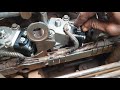 Mercedes Benz AXOR , problème de puissance , Défaut pompe module
 Mercedes-Benz Actros - Mechanical valve clearance adjustment | W930, W932, W933, W934
 how to adjust valve clearance of actross OM-501 11/3 V type engine
 shifting gear repair/Mercedes headtractor/Actros 1846..
 Valve Tappet Clearance Measuring & Adjusting|Malayalam
 Mercedes-Benz Actros engine production at the Mannheim Plant
 Mercedes-Benz Axor | Bleed shift mechanism on transmission 712-715
 Mercedes-Benz Actros - Rpm sensors on PowerShift 2 transmission | W930, W932, W934
 LKW Mercedes Benz Actros OM501LA Euro 5 (MP2/MP3) Motor Aufbau
 Мерседес Аксор - диагностика перед покупкой автомобиля.
 How to adjust Valve clearance actros 1841
 LB V8 engine 442 valve tappet adjustment
 Mercedes V 6 om 401 motor sibop ayarı
 Mercedes-Benz Actros - Flush metering device of exhaust aftertreatment system
 Mercedes-Benz Actros - How to replace the O-ring of the bell hub | W930, W932, W933, W934
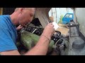 мерс 1117 регулировка клапанов.замена сидения и по мелочи
 Mercedes-Benz Axor - How to adjust plunger of the clutch actuator | W930, W932, W933, W934
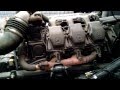 mercedes benz actros v6 automatico
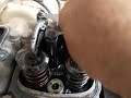 how to adjust valve clearance mercedez benz LB v8 twin turbo.