What are 2-Wire and 4-Wire Transmitter Output Loops?
▶ C'mon over to https://realpars.com where you can learn PLC programming faster and easier than you ever thought possible!
=============================
▶ Check out the full blog post over at
https://realpars.com/transmitter-wiring
=============================
In this video, we’re going to take a close look at 2-wire and 4-wire transmitters and discuss where they are used and why. We’re also going explore wiring configurations and how transmitters are connected to a PLC.
Before we get started, you might want to review our video called PLC Analog Inputs and Signals (https://realpars.com/plc-analog-inputs/).
A transmitter is an instrument that converts the small signal from a sensor to a signal which represents the variable being measured.
Transmitters come in all different shapes and sizes and connect with several types of sensors.
The transmitter output signal representing the variable being measured can be voltage or current.
A transmitter analog output loop contains the transmitter, power supply, and the receiving device which could be a PLC or DCS.
Just like any other instrument, a transmitter needs a power supply to operate. But, is it a 2-wire or a 4-wire transmitter?
The actual wiring connection between the transmitter and the power supply depends upon which type it is.
A 4-wire transmitter has 2 wires connected to a power supply, and 2 signal wires connected to the PLC.
The power supply can be AC or DC depending upon the vendor and model.
As its name states, a 2-wire transmitter has only 2 wires.
In a 2-wire current loop, the transmitter, DC power supply, and PLC are connected in series.
Not only are the 2 wires providing power for the transmitter, but they are also the signal lines!
Earlier we said that the transmitter output can be either current or voltage. Current is by far the most common transmitter output signal for many reasons.
One reason is if the wires between the transmitter and the PLC are very long, there could be significant voltage losses across these wires.
Regardless of the length of wire in a current loop, basic electrical theory tells us that the current is the same in the circuit regardless of where that current is measured.
=============================
Missed our most recent videos? Watch them here:
https://realpars.com/wireless-radio-modulation/
https://realpars.com/calibration/
https://realpars.com/flow-rate/
=============================
To stay up to date with our last videos and more lessons, make sure to subscribe to this YouTube channel:
http://goo.gl/Y6DRiN
=============================
TWEET THIS VIDEO https://ctt.ac/oEPnm
=============================
Follow us on Facebook: https://www.facebook.com/therealpars/
Follow us on Twitter: https://twitter.com/realpars
Follow us on LinkedIn https://www.linkedin.com/company/realpars
Follow us on Instagram https://www.instagram.com/realparsdotcom/
#Transmitter #RealPars #PLC
Видео What are 2-Wire and 4-Wire Transmitter Output Loops? канала RealPars
=============================
▶ Check out the full blog post over at
https://realpars.com/transmitter-wiring
=============================
In this video, we’re going to take a close look at 2-wire and 4-wire transmitters and discuss where they are used and why. We’re also going explore wiring configurations and how transmitters are connected to a PLC.
Before we get started, you might want to review our video called PLC Analog Inputs and Signals (https://realpars.com/plc-analog-inputs/).
A transmitter is an instrument that converts the small signal from a sensor to a signal which represents the variable being measured.
Transmitters come in all different shapes and sizes and connect with several types of sensors.
The transmitter output signal representing the variable being measured can be voltage or current.
A transmitter analog output loop contains the transmitter, power supply, and the receiving device which could be a PLC or DCS.
Just like any other instrument, a transmitter needs a power supply to operate. But, is it a 2-wire or a 4-wire transmitter?
The actual wiring connection between the transmitter and the power supply depends upon which type it is.
A 4-wire transmitter has 2 wires connected to a power supply, and 2 signal wires connected to the PLC.
The power supply can be AC or DC depending upon the vendor and model.
As its name states, a 2-wire transmitter has only 2 wires.
In a 2-wire current loop, the transmitter, DC power supply, and PLC are connected in series.
Not only are the 2 wires providing power for the transmitter, but they are also the signal lines!
Earlier we said that the transmitter output can be either current or voltage. Current is by far the most common transmitter output signal for many reasons.
One reason is if the wires between the transmitter and the PLC are very long, there could be significant voltage losses across these wires.
Regardless of the length of wire in a current loop, basic electrical theory tells us that the current is the same in the circuit regardless of where that current is measured.
=============================
Missed our most recent videos? Watch them here:
https://realpars.com/wireless-radio-modulation/
https://realpars.com/calibration/
https://realpars.com/flow-rate/
=============================
To stay up to date with our last videos and more lessons, make sure to subscribe to this YouTube channel:
http://goo.gl/Y6DRiN
=============================
TWEET THIS VIDEO https://ctt.ac/oEPnm
=============================
Follow us on Facebook: https://www.facebook.com/therealpars/
Follow us on Twitter: https://twitter.com/realpars
Follow us on LinkedIn https://www.linkedin.com/company/realpars
Follow us on Instagram https://www.instagram.com/realparsdotcom/
#Transmitter #RealPars #PLC
Видео What are 2-Wire and 4-Wire Transmitter Output Loops? канала RealPars
Показать
Комментарии отсутствуют
Информация о видео
Другие видео канала
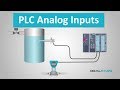 PLC Analog Inputs and Signals
 What is Ethernet?
 Top 13 Automation Engineer Interview Questions & Answers (Part 2 of 2)
 How to Read a P&ID? (Piping & Instrumentation Diagram)
 What are the Differences between DCS and SCADA?
 How to Measure Flow Rate with a DP Transmitter
 How to Determine the Motor Size for Your Project?
 How to Wire Discrete DC Sensors to PLC - Part 2
 Control box assembly (industrial automation) #3
 Variable Frequency Drives Explained - VFD Basics IGBT inverter
 What is HART Protocol?
 What is a Servo Motor and How it Works?
 What is the Difference Between PLC and DCS?
 What are PID Tuning Parameters?
 How to Wire Discrete DC Sensors to PLC - Part 1
 PLC Ladder programming #1 | Learn under 5 min | NO NC contacts | AND gate logic
 What is the Difference between VFD and Soft Starter?
 Differential Pressure Transmitter Explained
 What is Binary Coded Decimal (BCD) and How is it Used in Automation?
 What is Ethernet/IP?