Mini Pinball 05: Pop Bumpers, Targets, and More!
Felix works on a new revision to the PCB allowing electronic control of the game using a Teensy and an Arduino. Meanwhile, Ben works on some new mechanisms such as pop bumpers using Autodesk 360, 3D parts, and assembling it together to see how it will work and make adjustments to code using the Arduino IDE. Win Ben Heck’s Raspberry Pi Bitscope Mod: http://bit.ly/2wszu8b
Visit the Ben Heck Page: http://bit.ly/2vxjSTI
Make your own test equipment: http://bit.ly/2woKCER
Ben needs to make the ball loader mechanism to cycle through the states of the game. Meanwhile Felix is going to be working on a new revision of the PCB. They’re going to reorient it so that it resembles the way they want it to be in the actual game. They’re going to add some light drivers, some switch drivers, and also work on some code.
Felix has a breadboard that he’s worked up and now it’s time to make something that represents how it’s going to actually be in the machine. This includes reorienting the microcontroller to the side to give access to usb, figure out a place to put the screen, and redo some of the components. While Felix goes to work on the board, Ben is going to work on some new mechanisms, and they’ll touch base throughout the process to ensure both the mechanisms and board work together. Felix suggests swapping additional headers so they can swap between a teensy and an Arduino so it can potentially use both. An Arduino isn’t going to give you the same sound capability but it’s going to do the same logic and drive the LCD. It’s a 5 V system but they want to have 12 V going in to control the solenoids. The Teensy and Arduino have their own voltage regulators, but 12 V is too high for them.
Ben wires up an LED driver, the TI part current driver, and combined it with the chip registers for the switches. He’s attaching it to the SPI bus of the Arduino so that he can try reading and writing in the same operation to save time. If it works on the Arduino it will certainly work on the Teensy. The Teensy uses 4 bit mode for its SD card but it probably has additional SPI buses that they can access. Once he’s got the connections hooked up he just needs to hook up some test switches and LEDs so they can see if this thing works. Ben runs some test code. During the SPI cycle, 8 bits of data is sent to the slave device and data is also returned to the master device.
Once he’s done testing it’s time to work on the pop bumpers. You can check out how much current something is going to draw by checking its resistance. Even without putting in the power supply it’s possible to predict how much current this going to draw. He uses a piece of plywood to represent the playfield. Ben uses Autodesk Fusion 360 to draw the base solenoid, the rod, the playfield, and a representation of the spring. He also drew a reference of the rod in its down position as well as the bracket. He includes an actuator to move the ball around. After he gets his 3D printed parts printed he puts it together to see how it will actually work. Karen saves Ben some time on ordering metal shins by cutting one for him to use for testing purposes. Once its put together they test the contact discs with multimeter.
Finally Felix gives an update on his progress on the board. Serial input switches and the light driver are both in place. The MOSFETs are hooked up to the analog line 5,4,3,2, 1. They can look to the code to see if one of the bits changes on the switch line, use that to trigger the solenoid, and use that to test their pop bumper. Ben adds some more functions to the SPI test code using the Arduino IDE.
THIS VIDEO IS SUBJECT TO A DISCLAIMER AVAILABLE AT: http://bit.ly/2woRFx7
Видео Mini Pinball 05: Pop Bumpers, Targets, and More! канала element14 presents
Показать
Комментарии отсутствуют
Информация о видео
Другие видео канала
 Mini Pinball 06: Mechs + Microcontrollers
 Pop Bumper Assembly Basics
 Stronger and Faster: V8 Solenoid Engine
 Introduction to Electromechanical Pinball Machines and Their Schematics
 Mini Pinball 01: Project Mockup
 3 DIY IDEAS WILL ONE DAY HELP YOUR LIFE
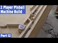 2 Player Pinball Machine Build, Part 12 (Ball Dispenser)
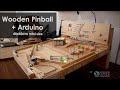 Wooden Pinball + Arduino DIY (40x40cm mini size)
 Here is why MOSFET drivers are sometimes essential! || MOSFET Driver Part 1 (Driver, Bootstrapping)
 Mini Pinball 09: Infrared Ball Detection
 DIY Star Trek Tricorder from Build Inside the Box
 Pop Bumper Removal and Reassembly
 How a Wind Up Music Box Works
 N64 Portable: It's Alive!
 You Cannot buy this Vacuum Tube Tester. You Build It!
 Ben Heck's BeagleBone Black Geocache
 Arduino Pinball Machine - 3d Printing & Lasercutting
 ADC LED Volume Meter with Arduino Uno - The Learning Circuit
 DIY Solenoid winding machine | Arduino project