[Tutorial] Model your building with Sketchup Make (Photo Matching) and use it in PV*SOL premium
http://www.valentin-software.com/services/fw/yt-val-en/dl-pvsolprem-en
In this tutorial you will learn how to use photo matching to model your building with SketchUp and use it in PV*SOL premium.
You will need:
- two Pictures of the building you like to model
- SketchUp Make or Pro
- PV*SOL premium 2018"
The pictures should be taken at a 45° angle from two opposite corners.
[…]
Start SketchUp.
Activate the used tools by right click the toolbar and select the tools as needed.
Open the drop down menu "Camera" and select "Match New Photo...".
Navigate to your "Images" folder and select an image.
The yellow square is the origin of the coordinates. The red line is the x-axis, green the y-axis and blue the z-axis.
Pull the yellow square onto a corner of the roof. The corner should be visible from both pictures.
Now drag the y-axes (green dashed line) on two parallel edges of the building and align them with the green squares at the end of the lines.
Do the same with the x-axis. The x- and y-edges of the house must be offset by 90° to the y axis.
To check the alignment, you can drag the origin to another corner of the house. The z-axis should coincide with a vertical edge of the house.
For adjusting you can use the x- and y-axis handles.
Check the alignment with other edges of the house.
When you hover with your mouse over the z axis, the cursor changes into two little arrows. Click with the left mouse button and change the scale by moving the mouse.
To complete the photo match click with the right mouse button and select "done".
Select the Rectangular Tool and draw the base surface of the front roof from the coordinate origin.
Select the Tape Measure Tool, move the mouse over the z-axis until a red square appears. Then click with the left mouse button and move the guide line to the center point (blue circle) of the edge.
Select the line tool and draw the front edge of the roof. Make sure that the end point of the line is on the guide line.
If you press the middle mouse button and hold it down, you can rotate the view by moving the mouse. Draw the remaining edges of the roof.
If you click on the blue tab, the scene changes back to the photo match view.
Left click three times to select the whole model. Then click with the right mouse button and select "Make Group".
If there is no volume, there is either an open area, a single line or an area within the body.
Check if the object has a volume. If there is no volume, there is either an open area, a single line or an area within the body.
Select the Rectangular Tool and draw the base of the remaining roof.
With activated Select Tool mark the edge and drag it with the Move Tool.
Draw a vertical guide line through the middle of the edge.
It's time to match the second picture.
Repeat the steps from the first photo match. The coordinate origin is located on the same roof corner and the axes must have the same alignment.
Adjust the house edge with the move tool.
Rematch the first picture by right click on the tab and select "Edit Matched Photo".
Adjust the x and y-axis a little bit so that the rear edge of the roof matches the picture.
When ready, right click and select "Done".
Using the Tape Measure Tool, click on the slanted roof edge and type in 0. The guide line should be on the edge.
Draw a vertical guide line through the center of the page. Select the Line Tool and draw the side of the roof from the intersection point of the guide lines.
Remove the guide lines by clicking on edit in the menu bar and select "Delete Guides".
Left click three times to select the whole model. Then click with the right mouse button and select "Make Group".
Check if the object has a volume. If there is no volume, there is either an open area, a single line or an area within the body.
Now we model the chimneys and roof windows. Select the Line Tool and draw on the surface of the roof. Move the cursor over the top edge of the roof and look for the pink 90° offset reference line.
Extrude the surface with the Push/Pull Tool by about 1 cm. To do this, select the tool, then click on the area and type in 0.01.
With the Line Tool you can model the chimney. When drawing the lines, make sure that you snap into the axes (x, y, z). The drawn line is colored according to the reference axes.
The colour of the surfaces is darker than the remaining surfaces. This is because the normal of the flats are twisted. The dark areas should be inside the object.
To invert, right-click on the surface and select "Reverse Faces".
In order for an object to become a solid body, there must be no surfaces within the object. The internal surface of the chimney must be removed. To do this, we select the area and delete it with the Delete key.
Left click three times to select the whole model. Then click with the right mouse button and select "Make Group".
[...]
Get the full transkript at:
http://www.valentin-software.com/services/fw/yt-channel-val/forum
Видео [Tutorial] Model your building with Sketchup Make (Photo Matching) and use it in PV*SOL premium канала Valentin Software GmbH
Показать
Комментарии отсутствуют
Информация о видео
15 февраля 2018 г. 17:17:10
00:23:04
Другие видео канала
![[Webinar] Introduction to system planning with PV*SOL – Part 2: 3D planning (English)](https://i.ytimg.com/vi/38yl0Nym3QI/default.jpg) [Webinar] Introduction to system planning with PV*SOL – Part 2: 3D planning (English)
[Webinar] Introduction to system planning with PV*SOL – Part 2: 3D planning (English) Bringing in imagery in SketchUp: Image, Match Photo, Watermark - Skill Builder
 World’s Greatest Architecture - Modeling the Farnsworth House - Sketchup 2019
![[Tutorial] Design a fast PV system with PV*SOL premium using Google Earth data (3D - Miami USA)](https://i.ytimg.com/vi/TiUaaZddJrI/default.jpg) [Tutorial] Design a fast PV system with PV*SOL premium using Google Earth data (3D - Miami USA)
[Tutorial] Design a fast PV system with PV*SOL premium using Google Earth data (3D - Miami USA)![[Tutorial] Polystring Connections & Power Optimizers in PV*SOL premium (SolarEdge, Tigo, Maxim.. )](https://i.ytimg.com/vi/I8wMA7p7dbk/default.jpg) [Tutorial] Polystring Connections & Power Optimizers in PV*SOL premium (SolarEdge, Tigo, Maxim.. )
[Tutorial] Polystring Connections & Power Optimizers in PV*SOL premium (SolarEdge, Tigo, Maxim.. ) Software Tutorial - PV*SOL premium - Map Import and Extrusion Of 3D Objects for fast PV Systems
![[Webinar] Introduction to system planning with PV*SOL – Part 1: 2D, Net Metering, Electric Vehicles](https://i.ytimg.com/vi/mjOUNnGxyp0/default.jpg) [Webinar] Introduction to system planning with PV*SOL – Part 1: 2D, Net Metering, Electric Vehicles
[Webinar] Introduction to system planning with PV*SOL – Part 1: 2D, Net Metering, Electric Vehicles Google SketchUp Tutorial Basics: How to build a simple house (door, windows, chimney, colouring)
 Tutorial desde cero con Sketchup - principios básicos -
 Quickly Model Stairs in SketchUp with Components - The SketchUp Essentials #10
 Surface Modeling with Fusion 360
![[Tutorial] PV*SOL premium 2017 - First Steps (to design a 3D PV system in PV*SOL premium)](https://i.ytimg.com/vi/xXXH1hULJWQ/default.jpg) [Tutorial] PV*SOL premium 2017 - First Steps (to design a 3D PV system in PV*SOL premium)
[Tutorial] PV*SOL premium 2017 - First Steps (to design a 3D PV system in PV*SOL premium) Tutorial: Aprende SketchUp en 10 minutos
 8 Ways to CREATE WINDOWS in SketchUp
 Como exportar uma imagem do Sketchup - Com qualidade alta - Sem render - Passo a Passo
 SketchUp Skill Builder: Reference Images
 Sketchup + Vray 3D living room Interior Design Speed up video
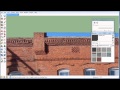 Using Photomatch in Google Sketchup
 Modeling Christchurch Cathedral Live in SketchUp
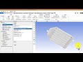 Flat plate/Solar Collector Tutorial (بالعربي)