DIY Ideal-diode circuit using transistors and MOSFET, schematic at the end :)
I made a buck converter, then replaced the diode with a MOSFET and created a signal to drive the MOSFET using some transistors, resistors en diodes.
Next thing to do is build a bigger converter and start load-testing the circuit.
https://krakkus.com/2023/04/25/diy-ideal-diode-circuit-is-great-for-improving-dc-converter/
Видео DIY Ideal-diode circuit using transistors and MOSFET, schematic at the end :) канала krakkus
Next thing to do is build a bigger converter and start load-testing the circuit.
https://krakkus.com/2023/04/25/diy-ideal-diode-circuit-is-great-for-improving-dc-converter/
Видео DIY Ideal-diode circuit using transistors and MOSFET, schematic at the end :) канала krakkus
Показать
Комментарии отсутствуют
Информация о видео
Другие видео канала
 PyDuino add IO to a PC
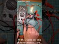 eBay converter controller
 The 74HC595 shift register
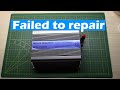 Today I learned nothing :) - Inverter repair failed - Part 1
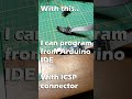 ATTINY84 for dual PWM signal
 Motorized Zoom Lens #2 - Motors working, IR filter installed
 How to make tflite-model-maker work again in 2024 - for Windows
 Make a 12V car light go 24V - two filaments in series
 How to use the IR2125 MOSFET gate driver
 Op-amp as comparator & voltage follower
 Resistor simulator - v0.3a
 Hacking a DC-to-DC converter from eBay
 Programming an ATTINY from an Arduino
 MOSFET gate driver using transistors - sorta works
 DC converter hack #4 - Boost converter
 How to add dead-time to PWM
 9 ways to drive a MOSFET, with examples
 8 bit 8 resistor digital to analog converter
 Bootstrap circuit for high side MOSFET driving
 Build your own digital-to-analog-converter in under 10 minutes.