RPM Meter with Hall Effect Square Encoder Sensors
RPM meter with quadrature encoder using Hall effect sensors.
I use KY-035 sensors that have an AH49E analog sensor. For each motor I have placed two mechanically separated sensors in quadrature to determine the direction of rotation.
With the use of external interruptions I control the state of sensors 1 of each pair and with internal interruptions (Timer1) I count the time of the period to determine the frequency and the RPM. It used exponential decay by not detecting changes in sensor 1 of each encoder, either because the speed has dropped considerably or the motor has stopped.
On each axis of the motors I have improvised an encoder with neodymium magnets.
For starting and turning control of each motor, I use operational amplifiers (LM324N) with a joystick and a driver (L293N and L298N).
Last but not least, I have used a Schmitt Trigger inverter (SN74LS14N) to nullify the transient effect of each sensor, which avoids false readings and thus obtain with enough precision the revolutions and direction of rotation of each motor.
Code: https://github.com/DrakerDG/RPM_Meter_Direction_V3
Reference:
https://youtu.be/BAfxA7JvHsE
https://youtu.be/epU-XlbErkY
https://youtu.be/dTuYLGqXNRg
https://youtu.be/QZ8umuWt5Zw
https://youtu.be/iQrE2IDGjI8
https://youtu.be/oSBpj-XV1_o
Follow me:
Youtube: https://cutt.ly/ZhPSGJ9
Facebook: https://cutt.ly/ChPSJdC
Instagram: https://cutt.ly/QhPSKoq
Видео RPM Meter with Hall Effect Square Encoder Sensors канала DrakerDG Robotics
Показать
Комментарии отсутствуют
Информация о видео
Другие видео канала
 HALL Effect SENSORS - Linear,UniPolar,BiPolar
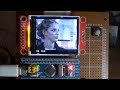 Smooth video playback on STM32 and ST7735
 Sim Racing Pedals with Hall Sensors
 Salvaging Hall Effect Sensors and Neodymium Magnets - Build an RPM-meter
 VCMでライン追従 ロボトレーサ
 Tachometer (RPM Measurement) using IR Sensor & Arduino
 Inductive and Hall Effect RPM Sensors Explained
 Control a Stepper Motor with Hall Effect Switches
 What is Hall Effect and How Hall Effect Sensors Work
 ARDUINO Sensor de PRESION MPX2050 ▌Pressure Sensor ▌
 Homemade joystick
 What is Encoder?
 Using the ACS712 Hall Effect Current Sensor Module (part 2)
 homemade joystick hall sensors terminado, finished
 How Rotary Encoder Works and How To Use It with Arduino
 Hall effect magnetic levitation
 Essentials of Hall Effect Sensors
 Hall Effect - Sixty Symbols
 TOP 4 ELECTRONICS PROJECT WITH TRANSISTOR, LED, THYRISTOR, RELAY, DIODE
 How to make Arduino based Digital Tachometer │RPM Counter simple DIY tutorial