Inductive and Hall Effect RPM Sensors Explained
Hall effect sensors have an advantage over inductive sensors in that, while inductive sensors respond to a changing magnetic field which induces current in a coil of wire and produces voltage at its output, Hall effect sensors can detect static (non-changing) magnetic fields.
Видео Inductive and Hall Effect RPM Sensors Explained канала Automotive Basic Knowledge
Видео Inductive and Hall Effect RPM Sensors Explained канала Automotive Basic Knowledge
Показать
Комментарии отсутствуют
Информация о видео
Другие видео канала
 How Do Hall Effect Sensors Work? - The Learning Circuit
 What is Hall Effect and How Hall Effect Sensors Work
 How Engine Sensors Work: Crankshaft, Camshaft, ABS. Magnetic Inductive Sensors.
 Inductive Sensor Explained | Different Types and Applications
 CAM and CRK & Wiring Diagrams
 How to test a cam or crank sensor with a voltmeter - hall effect type - (Quick Tips)
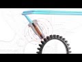 Wheel Speed Sensor Operation & Testing
 🛠 Sensory Overload - Hall Effect vs Reluctor | TECH TUESDAY
 How to Test Crankshaft and Camshaft sensors 1
 Crankshaft position sensor CKP Simulation Animation explanation https://commonrail.bg/
 HALL Effect SENSORS - Linear,UniPolar,BiPolar
 ABS Wheel Speed Sensor
 Electronics 101: The Hall Effect explained
 EVERY ENGINE SENSOR EXPLAINED - MAF, MAP, IAT, TPS, 02, NOx, EGT - How it works, location, OBD2 code
 Crank and Cam Sensors
 Hall effect cam/crank sensor operation and testing Part 2 (an SD Premium video)
 Hall Effect explanation and how hall effect sensor works. Checking of Hall effect sensor.
 Inductive Sensors - PNP vs NPN - N.O. vs N.C. - Datalogic
 P0340 Cam Sensor Circuit Code (New Sensor Installed)