Computer Inputs: Pull-Up and Pull-Down Circuits
There are two types of circuits that are used for computer input signals: Pull-up and pull-down circuits. This video explains how these circuits work so that you can know how to test and diagnose sensor circuits.
Видео Computer Inputs: Pull-Up and Pull-Down Circuits канала Justin Miller
Видео Computer Inputs: Pull-Up and Pull-Down Circuits канала Justin Miller
Показать
Комментарии отсутствуют
Информация о видео
Другие видео канала
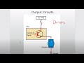 Computer Outputs: High-Side and Low-Side Drivers
 Pull-up and pull-down resistors
 Pull Up and Down Resistors for Floating Inputs- Simply Put
 Sensor grounds and the 5v reference circuit (a 2016 ScannerDanner Premium video)
 Camshaft and Crankshaft Position Sensor Waveform Analysis
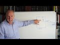 Pull-up and pull-down resistors
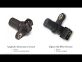
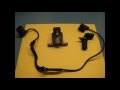 Pull Down and Pull up Type Hall Effect Sensor Circuit for cars (simplify)
 Floating Pins, Pull-Up Resistors and Arduino
 RSD Academy - Open Collectors and Pull up Resistors
 Electronics 201: Pull-Up and Pull-Down Resistors
 Short and sweet: pull up/pull down resistors explained
 Hall effect cam/crank sensor operation and testing Part 1 (an SD Premium video)
 Using the PicoScope Built-in Waveform Generator
 Pull Up Resistor Tutorial | AddOhms #15
 Using Triggers to Capture Better Waveforms
 Setting up 2000 series PicoScope for automotive use
 Arduino Tutorial 27: Understanding Pushbuttons and Pull Up and Pull Down Resistors
 Circuit ID and Integrity Testing Part 4 (SD Premium)
 Overlaying Multiple Waveforms on the PicoScope (Reference Waveforms)