Communication - Collaboration Diagram - Step by Step Guide
Welcome to Master2Teach Step by Step Guide
In this video, you’re going to learn
1. What is Communication/Collaboration Diagram?
2. How to draw Communication Diagram Step By Step.
3. Example of drawing communication diagram with Case Study
What is Communication Diagram? First of all, I would like to make clear that it is also known as a Collaboration Diagram. Communication Diagram is used to show how objects interact to perform the behavior of a particular use case or a part of a use case.
Use Case Diagram: https://www.youtube.com/watch?v=sQgoFjxSdxo
After the expanded use case description of the major use cases, we start the communication diagram.
As we are drawing the design in an object-oriented way, a collaboration diagram describes a pattern of interaction among objects. It shows the objects participating in the interaction by their links to each other and the messages that they send to each other. What is Class and Its Objects.
Actually Collaboration diagrams are used by designers to define and clarify the roles of the objects that perform a particular flow of events of use cases. They are the primary source of information used for determining class responsibilities and interfaces.
We will know how these objects of different classes will interact and flow messages with each other in stepwise. All showing this kind of information in the diagram is the Collaboration diagram. Its main purpose is to visualize the interactive behavior of the system.
We all know that, objects of the classes communicate by sending and receiving messages.
How to Draw a Collaboration Diagram?
First Step:
Go through a Use Case Description and list the Domain Classes.
The Major class which needs to define while executing the use case are the domain classes.
How to find Domain Classes?
Let’s take the same use case example which we have drawn in the previous use case tutorial.
It’s a College Student Records System Application where students can enroll online in the college themselves from home.
The high level and expanded use case description of the use case Enroll Student are.
As we knew, in expanded we write the interactive description between actor and system.
1. The new student provides personal details for enrollment.
2. System Response and shows available course as options
3. Chooses the best course among the available course
4. The system provides a confirmation message of enrollment to students.
Now first of all, find the NOUNS from the Description and list those which are important to the processing.
If the system has to process data about the type of person or object named, then this is probably a relevant class of objects like Student data need to store, Course option should be provided and chosen courses data need to process.
The Possible Classes for the Use Case Enroll Student are
Student
Course
Enrollment
After successfully identifying all domain classes, draw an object symbol for each of the Domain Class Objects. Object symbols are represented in the Rectangle box with : followed by Domain Class Name.
Like- :Student, :Enrollment, and :Course and Don’t forget to underline the text.
The third is Drawing Control Object. Add a control object in the diagram. Note that the name of the controller object is the same name as the use case name.
Here we are taking an example as Enroll Student use case, so the controller object name must be :Enroll Student.
The next step which is the fourth step is Drawing Boundary Object. Boundary objects will also have the same name as the Use Case name with the addition of UI at last. Like
:EnrollStudentUI. This object is for the user interface.
Now the Fifth step, where we draw the Actor just beside the Boundary Object because actor interacts with the system interface.
Actor notation is similar to the use case diagram which is represented by a human stick image.
The sixth step which is adding associations on it. Draw a line connecting any pair of Objects which need to know about each other – In order to be able to send a message. Perhaps to give an instruction or get information back.
Now next step is adding messages to the diagram.
In this way, we can draw the collaboration diagram following step by step.
Note that the collaboration diagram depends on how the analyst chooses to allocate responsibilities between the objects and on the chosen order of processing. It would be possible to draw an entirely different collaboration diagram to do the same task.
Collaboration and Sequence Diagrams are the type of Interaction diagram and these are isomorphic which mean you can convert one diagram into another diagram.
SUBSCRIBE to our YouTube channel for more videos: https://www.youtube.com/c/Master2Teach?sub_confirmation=1
Like us on Facebook: https://www.facebook.com/master2teach
For more content go to https://master2teach.com/
E-mail: master2teach@gmail.com
Видео Communication - Collaboration Diagram - Step by Step Guide канала Master2Teach
Показать
Комментарии отсутствуют
Информация о видео
Другие видео канала
 Activity Diagram - Step by Step Guide with Example
![Use Case Diagram Tutorial : Draw using just [4 Key Components]](https://i.ytimg.com/vi/oesoKbn0yeA/default.jpg) Use Case Diagram Tutorial : Draw using just [4 Key Components]
Use Case Diagram Tutorial : Draw using just [4 Key Components] Sequence Diagram - Step by Step Guide with Example
 All About UML Activity Diagrams
 Class Diagram - Step by Step Guide with Example
 UML 2 Communication Diagrams
 How to make communication diagram with example
 10 ways to have a better conversation | Celeste Headlee
 UML Collaboration Diagram with solved Example || MCS-032 || MCSL-036
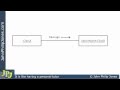 UML Collaboration Diagram
 Collaboration or Communication Diagram
 7 Ways to Make a Conversation With Anyone | Malavika Varadan | TEDxBITSPilaniDubai
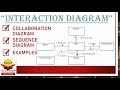 Interaction Diagram with example | Collaboration Diagram | Sequence Diagram
 what is a state transition or state machine diagram?how to make it
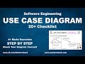 Use Case Diagram - Step by Step Checklist with Example
 UML Class Diagram Tutorial
 How To Speak by Patrick Winston
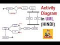 UML Activity Diagram with solved example and notes(HINDI) || IGNOU || MCS-032
 How to Make a UML Sequence Diagram
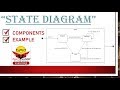 State diagram with example