Automatic Door Bell Ringer Project Multisim
Circuit Operation
The IR LED and the phototransistor is placed near such that, in normal operation, the phototransistor doesn’t receive any light and doesn’t conduct. Thus, the transistor (as it doesn’t get any input voltage) doesn’t conduct.
Since the timer input pin 2 is at the logic high signal, it is not triggered and the buzzer doesn’t ring, as it doesn’t receive any input signal. If a person approaches the door, the light emitted by the LED is received by that person and gets reflected back. The phototransistor receives this reflected light and then starts conducting.
As this phototransistor conducts, the transistor gets biased and starts conducting too. Pin 2 of the timer receives a low logic signal and the timer gets triggered. As this timer gets triggered, a high logic pulse of 9V is generated at the output, and when the buzzer receives this pulse, it gets triggered and starts ringing.
#LearnLabview
#LearnElectronic
#learnProgramming
#futureTechnology
Видео Automatic Door Bell Ringer Project Multisim канала LabVIEW & MULTISIM
Показать
Комментарии отсутствуют
Информация о видео
Другие видео канала
 Automatic Washroom Light Project Using MULTISIM
 Essential Electronics Components that you will need for creating projects!
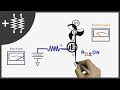 MOSFETs and How to Use Them | AddOhms #11
 Load and visualize .csv data in LabVIEW
 Simple Door Alarm Circuit | Make Very Easy
![Simple Electronic Project [NEW]](https://i.ytimg.com/vi/wM98biI0lu0/default.jpg) Simple Electronic Project [NEW]
Simple Electronic Project [NEW] logic gate example/ Tea and coffee vending machine using logic gates
 How to Make an IR Proximity Sensor | Touchless Door Bell
 Tinkercad Arduino Tutorials: Door Buzzer Using Ultrasonic Sensor
 Transistors Explained - How transistors work
 Password Security System (Mini project) | STM32 | HAL | Keypad | LCD
 How to Use Multisim/Circuit Simulation in Multisim ||Urdu
 How to Use a Breadboard
 How To Create Animated Videos With PowerPoint | Beginners Guide
 DIY Simple Door Security Alarm System | Electronic project |
![Digital Logic Design Project Simulation[Spring 19-2020] AIUB || Fire Alarm Security System](https://i.ytimg.com/vi/KG4Fv83L-Io/default.jpg) Digital Logic Design Project Simulation[Spring 19-2020] AIUB || Fire Alarm Security System
Digital Logic Design Project Simulation[Spring 19-2020] AIUB || Fire Alarm Security System Temperature Based Fan Speed Controller project | Arduino Uno - IOT
 Security System Using X-OR & NOR gate || DLD Project
 MOBILE PHONE CHARGER CIRCUIT USING MULTISIM SOFTWARE
 DIY Automatic Feeder for Pets with Digital Timer