Beep codes, POST Cards and PSU Testers
In this video from ITFreeTraining, I will be looking at some of the tools that you can use to troubleshoot a computer that is failing to start up. These tools will allow you to fix problems you may not have normally been able to and potentially speed up the troubleshooting process.
Download the PDF handout: http://itfreetraining.com/handouts/ap/1b67.pdf
In This Video
0:16 Generally, when a computer is failing to start up, you will get a black screen. To troubleshoot this, I will first look at a power supply tester. If you have a dead computer, the power supply tester will quickly allow you to test if the power supply is the problem. The power supply tester will also allow you to test for a power supply that is malfunctioning, for example not out putting the correct voltages.
Next, I will look at the start-up beeps. Shown here is an example of a PC speaker that can be plugged into a motherboard. When there is a problem, the PC speaker is used to emit a number of beeps. The number of beeps will inform you what the problem may be. You may also get a text message giving you an idea what the problem is.
Although beep codes and text errors are useful, sometimes these can be misleading or maybe all you are getting is a black screen and no beeps. For example, a malfunctioning device can disrupt the POST process forcing the computer into an endless loop. This can look like the computer is dead when in fact it is not.
The next tool that I will look at is a POST card. The POST card plugs into the motherboard. The POST card contains a number of light-emitting diodes that display information about the computer. However, most importantly it displays a code which indicates which device the POST is currently testing. This information can be invaluable in the troubleshooting process.
The problem that you will come across is trying to find documentation for what the codes mean. Every BIOS manufacturer and different versions of BIOS will use different codes. To start with, I will have a look at the power supply tester.
Power Supply Tester
2:03 When troubleshooting, consider it as a logical problem. Most of the time a failed component will be causing the problem and will need to be replaced. On rare occasions you may have two failed components, but usually it will be only the one. It is just a matter of working out which component is not working. To do this, often it helps to find out what is working, eliminate it leaving what is left as possibly faulty.
The power supply tester allows you to test a power supply and its cables to ensure it is working and outputting the correct voltages. Shown here is the power supply tester. You can see next to it the powers supply that I will be testing.
To start with, I will locate the P1 or ATX connector and plug it into the power supply tester and switch on the power supply. This is a 20 or 24-pin connector. Later in the course I will be going into more detail about the different connectors used inside a computer. It is the largest connector attached to the power supply and plugs into the motherboard, so it is easy to find.
You will notice that once it is plugged in, the LCD screen lights up and shows all the voltages the power supply is currently outputting. For positive voltages the tolerance is five percent and for negative voltages it is ten percent. The PG, or power good signal, needs to be between 100 and 500 milliseconds. The power good signal is a signal given to the motherboard when it is switched on and has had time to stabilize. When the power is cut to the power supply, the power good signal should drop immediately. The power supply will still have some power stored in its capacitors. This gives the computer a few milliseconds notice that the power has been switched off and it is running off capacitors. This very small amount of notice gives the computer a very small amount of time to shut down its components.
You can hear that the power supply tester is beeping. On the screen there are two L’s flashing. If you get an LL or HH on the screen there is a problem with the power supply. In this case however, I know the problem is that I need to plug in the P4, otherwise known as the EPS connector.
As CPUs started using more power, the P1 connector could not provide enough power to the motherboard. Thus, a 4-pin or 8-pin connector was added. In some cases, your 8-pin connector may be able to be divided into two 4-pin connectors.
Description to long for YouTube. Please see the following link for the rest of the description http://itfreetraining.com/ap/1b67
References
“CompTIA A+ Certification Exam Guide Tenth Edition” pages 193-216
“ATX” https://en.wikipedia.org/wiki/ATX
Credits
Trainer: Austin Mason http://ITFreeTraining.com
Voice Talent: HP Lewis http://hplewis.com
Quality Assurance: Brett Batson http://www.pbb-proofreading.uk
Видео Beep codes, POST Cards and PSU Testers канала itfreetraining
Показать
Комментарии отсутствуют
Информация о видео
Другие видео канала
 Motherboard Connectors
 Desktop Motherboard Repair Tutorial
 BIOS
BIOS Motherboard Debug LED - TL460s Plus Overview
 How to repair dead dry battery at home , Lead acid battery repairation
 SATA and eSATA
 CPUs and CPU Sockets
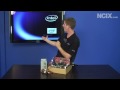 PC Troubleshooting No Post Diagnosis (NCIX Tech Tips #54)
 How to Clear the CMOS - Reset the BIOS & Why
 29 Things That Exist Only in Japan
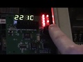 PC BIOS POST Testing/Diagnostics Card (ISA-PCI)
 RJ45 and RJ11
 Computer beeps 3 times and refuses to power up Fix
 Active and Passive Cables
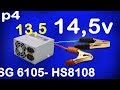 convert atx power supply to bench power supply, ATX PSU hack 13,8v, 14,5v Alf
 BIOS and UEFI Setup
 Building a PC... using only Wish.com
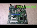 Fixing A Dead Server Motherboard + Troubleshooting Tips
 Universal Serial Bus (USB)
 Clear CMOS Settings