Dual Trigger Pad - DIY
This video is about building a dual trigger system for less than 100€.
Find V-drum Tips on:
Facebook: http://goo.gl/sW6z3S
Twitter: http://goo.gl/svH95f
Webpage: http://www.v-drumtips.com
Wiring diagram: http://goo.gl/KEu7PE
✭ ✭ My E-drum Headphones: http://amzn.to/2swspFA
✭ ✭ My favourite USB –Midi Interface: http://amzn.to/2Bvc4DQ
Buy the Roland MH-2 Mesh Head Here:
US: http://amzn.to/2oZya7t
UK: http://amzn.to/2qrkFQ6
DE: http://amzn.to/2pByCgj
Buy EZdrummer2 here: https://goo.gl/VWpdr9
Metal Angles: http://goo.gl/sCl8Bo
Trigger cone& piezo: http://goo.gl/YAv35J
Decoupler: http://goo.gl/nR7b4F
Rim silencer: http://goo.gl/AJL0DV
Music by David Hillard: http://goo.gl/mkmoK6
We bought this 14-inch pearl rhythm traveler pad. It is a second hand pad and perfect for modifications. The interesting part of the pad is however the trigger system. Therefore we need this trigger cone and a decoupler from r-drums to desolate the head trigger from the pad. Head and rim piezo also from r-drums, an adhesive dot to apply the piezo, a stereo jack plug, 6 x m4 screws including big washers and lock washers and these metal angles.
First we’ll remove head and rim. We take off a lug screw and a second one at the opposite to attach 2 of the angles. We use m4 screws with big washers. The original screws are too short.
It is important to measure the exact distance between the holes. The main component of the pad will be an aluminium disc. The disc is from a German Online store, specialist in metal sheet cutting. It should be 10mm smaller than the drum inner diameter, but still big enough to fit the holes of the angles.
The purpose of a smaller disc is that we are still flexible with the way we attach the angle. We can mount it in 4 different variations. There is also enough space for the second lug screw.
Our pad has 6 lugs. That means we need 6 holes with an offset of 60°. The disc is protected with a protection layer, which is writeable. This is the spot for the jack plug. It shouldn’t be too far away from the piezos, duo to their cable length. The 40 by 40 mm square is required for the decoupler foam.
The holes at the angles have a diameter of 5mm. As a result we’ll drill 5mm holes into the aluminium disc. Aluminium is not only light, it is also really easy to work with. We attached a hover pipe near the drill bit, to get rid of the aluminium dust immediately. Just getting rid of the edges with a countersink.
Now we can try out if the holes fit with the applied angles.
Time to cut out the square in the middle of the pad. The protection layer get’s removed only at this spot. We want to use spray adhesive to paste the decoupler onto the disc. This way we only spray the required spot.
The decoupler has to be exactly in the middle of the disc, to get the best trigger result.
Spay adhesive is a perfect way for applying foam.
We get rid of the layer after few hours of waiting time.
The decoupler has a little stainless steel disc. It is the perfect surface for attaching the piezos.
Now we’ll need the piezos, the bigger one is for the rim and gets pasted via double layered adhesive tape, near the centre of the disc. We decided to not use an adhesive dot here to have a more sensitive rim trigger. The smaller head trigger gets attached with an adhesive dot specially made for this purpose. It has to be exactly in the middle of the steal disc. Time to paste the smaller head piezo.
We screw on the jack plug, which points down.
The cables will be bunched with a heat shrinking tube before the soldering process begins. They get soldered to the jack. It is really important to connect them in the right way. You can download the wiring diagram in the video description.
Shrink the head shrinking tube with a hot air gun or a lighter.
We have to mount the angles first. They should be mounted in a way that the cone has the correct height and stays moveable either up or down.
The height of the cone, piezo and decoupler is 63 mm. This means the disc has to be around 62mm lower than the bearing edge of the drum.
In this case we need a gap between angles and aluminium disc. We take a longer m5 screw including washers and extra nut. We mount it this way to lift the angle up.
As you can see there is still enough room for the lower screw and the fine-tuning of the trigger cone.
The upper lug screws and the ones of the holder have to be removed.
Now we can finally install the trigger system. It is really tight which means we worked accurately. The m4 screws need lock washers and big washers. We screw them but won’t tighten them yet. The holder screws need to be applied now.
Now we need the trigger cone. We cut a little gap into it, to give the cable of the piezo some space. The top of the cone has to be 1,5mm higher than the bearing edge of the drum. The sticky tape is the marker.
Видео Dual Trigger Pad - DIY канала Vdrum Tips
Показать
Комментарии отсутствуют
Информация о видео
Другие видео канала
 Low Budget Trigger Pad DIY (E-drums)
 Dual Trigger System (E-drums)
 How Piezos and Switches work: (edrums demystified)
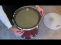 DIY Electric Acoustic Drum Triggers Tutorial for eDrums
 Badass Metal Drumkit converted to E Drum
 Roland VH 12 & VH-13 Setup/Comparison
 Cara Membuat Pedal Drum Dari Kayu 🥁
 A "Proper" Explanation of Drum Triggers
 Homemade Drums 2.0 | 4- Reforma dos pads + pad dual zone
 9 Things You Need To Know About Drum Triggers
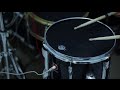 CONVERTENDO BATERIA ACÚSTICA EM ELETRÔNICA Parte 1 - (DIY)
 E-drum Conversion Part 2 (Wrapping)
 Alesis Mesh Head Mod
 How to replace a trigger cone? (Roland)
 Cara Membuat Drum Elektrik Sederhana Dari Keyboard PC
 R-Drums RTB Review (acoustic to electronic snare conversion)
 How to Make DIY eCymbal Pads from Plastic Plate for Electronic Drums
 Roland Cy-5 or Vh-11?
 Dual Trigger internal Roland ( 3 zone ) DRUM Brasil
 Building the Best E-Bass Drum