Multiple Servo Control with Potentiometers and Arduino
In this tutorial, we will learn how to use multi-servo with potentiometer. We will control 4 pcs servo motor with 4 pcs potentiometer. You can implement your robotic arm projects with reference to this tutorial. Of course we will use external battery / power when doing this.
In the next tutorial, I'll show you how to control servo motor with joystick. Do not forget to subscribe. Thank you for your support. I did not share the code because it is short and it varies according to the number of servo,potentiometer. You can write code by watching the tutorial. This is a better way to learn. I will continue to share long and complex codes.
Required Hardware:
Arduino Board
https://goo.gl/UyGYeF
https://amzn.to/2LZr6t4
Servo Motor x4 :
https://goo.gl/iOkPgu
https://amzn.to/3avwe1N
10k Potentiometer x4:
https://goo.gl/c90Uix
https://amzn.to/3dlgYq1
Jumper Wires :
https://goo.gl/VRzUN4
https://amzn.to/3doetmT
Breadboard:
https://goo.gl/yCa8hX
https://amzn.to/3qxLxwm
Recommended Items:
Use Your Muscles in Project - https://amzn.to/3wdL45C
37 Sensor & Module Packages - https://amzn.to/3m66WeQ
Try this Robot Arm - https://amzn.to/3fq8DCl
Best Resin 3D Printer - https://amzn.to/39tY8KB
Arduino Compatible Kits - http://bit.ly/2J2AFF7
Banggood Spring Sale - https://bit.ly/3slMbOn
Connections:
The external battery VCC / GND connect to the breadboard.
The Arduino GND connect to the breadboard's GND input
The servo connections we use in this project are as follows;
Orange Input - Signal Input
Red Input - Power Input (VCC)
Brown Input - Ground Input(GND)
The potentiometer connections we use in this project are as follows;
Two other pins are power (VCC) and ground (GND)
Middle pin is signal pin
The Servo1 VCC and GND connect to the breadboard's VCC / GND inputs
The Servo1 Signal connect to the Arduino Digital PWM 3
The Servo2 VCC and GND connect to the breadboard's VCC / GND inputs
The Servo2 Signal connect to the Arduino Digital PWM 5
The Servo3 VCC and GND connect to the breadboard's VCC / GND inputs
The Servo3 Signal connect to the Arduino Digital PWM 6
The Servo4 VCC and GND connect to the breadboard's VCC / GND inputs
The Servo4 Signal connect to the Arduino Digital PWM 9
The Potentiometer's one outer pin connect to the breadboard VCC input
The Potentiometer's other outer pin connect to the breadboard GND input
The Potentiometer's middle pin connect to the Arduino Analog 1-2-3-4 input
Source: http://bit.ly/2DD7bts
Web Site: www.mertarduino.com
Social Media:
https://www.instagram.com/mertarduino/
https://www.facebook.com/mertarduino/
Видео Multiple Servo Control with Potentiometers and Arduino канала MERT Arduino & Tech
Показать
Комментарии отсутствуют
Информация о видео
Другие видео канала
 How to Make Servo Robotic Arm using Arduino.
 Make 5 in 1 Robot
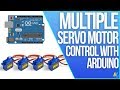 Multiple Servo Control with Arduino Uno R3
 Multi Servo Motor Control via Bluetooth Using Android App | Arduino and App Inventor
 How to assemble and control a 4 DOF robot mechanical arm kit with Arduino | Step by step
 Arduino Tutorial 30: Understanding and Using Servos in Projects
 Sinhala Arduino Tutorial 06 - Servo Motors
 Multiple Servo Motor Control Arduino Tutorial
 Electronic Basics #25: Servos and how to use them
 Robot Arm & Controller - Building the DFRobot 5 DOF Robot Arm
 Multiple Servo Motor Control with Joystick and Arduino
 Complete guide to PCA9685 16 channel Servo controller for Arduino with code V1
 6 DOF Robotic Arm Arduino Circuit
 Curso de Arduino #11 - Servomotores
 Arduino Sinhala Tutorial 10 | PWM | AnalogWrite | RGB LED | myhub.lk #myhubLK
 Make Voice Notification Warning Project
 Controlling the position of a continuous servo with a potentiometer and arduino
 How To Make Arduino Robotic Arm Controlled with Smartphone - Cardboard DIY
 Robokits Arduino Uno based 18 Servo Controller board - Part-2 ( Bluetooth Control)