FFT Tutorial
Tony and Ian from Tektronix present a FFT Tutorial (Fast Fourier Transform) covering what is FFT, an explanation of the FFT function as well as different FFT applications. They explain how the FFT works with a FFT example and show an oscilloscope demo to demonstrate how helpful the FFT can be.
What is FFT?
In the video, "How to Use an Oscilloscope" (http://youtu.be/tzndcBJu-Ns), an oscilloscope was used to look at a single sine wave. But when you connect an oscilloscope to a live circuit, you rarely see something so simple. On real projects, you're usually looking at combinations of signals. The FFT lets you break down the data you've captured and see what it's made of.
FFT Example
One FFT example is when you want to understand your own signal. If you're designing a circuit board, and you attach your oscilloscope probe at the antenna, you're expecting the signal at the antenna to be at the frequency you designed it for.
What you actually see is an extra signal. That extra signal is at a different frequency, and it's one you didn't expect to see. You'll notice you can't see it on the regular oscilloscope display before the FFT because it's 1/1000th the amplitude of the signal you're expecting.
In the video FFT example, the cause is likely harmonic distortion since it's a multiple of the frequency we're expecting. If it were an exact multiple of some known clock board, then the likely cause would be cross-talk.
How FFT Works
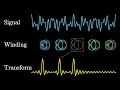
The FFT helps you see what kinds of signals are present in your system. Specifically, it breaks down your complicated signal into separate sine waves. Any signal at all can be thought of as the sum of different sine waves (the Fourier Transform). The oscilloscope's FFT, or Fast Fourier Transform, is just one method of performing this operation.
FFT Applications
Most oscilloscopes have a FFT built into their math system these days. In the oscilloscope featured in the video, you just press Math and then turn on the FFT option. Then you can set various properties of the analysis, like the frequency range you want to look at.
In the video example, you can see that same series of frequency-domain spikes stretching out. This is kind of a pared-down version of what you'd see on a spectrum analyzer. If you wanted something more like a real spectrum analyzer, you could use a mixed domain oscilloscope with a dedicated RF channel.
The mixed domain oscilloscope in the video shows a FFT of the signal from a completely separate input. The idea is that you use the regular analog channels to look at the various signals on your board, and use the RF channel to see what's actually coming out of your antenna port.
For more FFT Information go to: www.tek.com/fft-basics
Also, keep an eye out for the next video in this series, covering a FFT example where the FFT function is used to measure musical signals in front of a live audience.
Видео FFT Tutorial канала Tektronix
What is FFT?
In the video, "How to Use an Oscilloscope" (http://youtu.be/tzndcBJu-Ns), an oscilloscope was used to look at a single sine wave. But when you connect an oscilloscope to a live circuit, you rarely see something so simple. On real projects, you're usually looking at combinations of signals. The FFT lets you break down the data you've captured and see what it's made of.
FFT Example
One FFT example is when you want to understand your own signal. If you're designing a circuit board, and you attach your oscilloscope probe at the antenna, you're expecting the signal at the antenna to be at the frequency you designed it for.
What you actually see is an extra signal. That extra signal is at a different frequency, and it's one you didn't expect to see. You'll notice you can't see it on the regular oscilloscope display before the FFT because it's 1/1000th the amplitude of the signal you're expecting.
In the video FFT example, the cause is likely harmonic distortion since it's a multiple of the frequency we're expecting. If it were an exact multiple of some known clock board, then the likely cause would be cross-talk.
How FFT Works
The FFT helps you see what kinds of signals are present in your system. Specifically, it breaks down your complicated signal into separate sine waves. Any signal at all can be thought of as the sum of different sine waves (the Fourier Transform). The oscilloscope's FFT, or Fast Fourier Transform, is just one method of performing this operation.
FFT Applications
Most oscilloscopes have a FFT built into their math system these days. In the oscilloscope featured in the video, you just press Math and then turn on the FFT option. Then you can set various properties of the analysis, like the frequency range you want to look at.
In the video example, you can see that same series of frequency-domain spikes stretching out. This is kind of a pared-down version of what you'd see on a spectrum analyzer. If you wanted something more like a real spectrum analyzer, you could use a mixed domain oscilloscope with a dedicated RF channel.
The mixed domain oscilloscope in the video shows a FFT of the signal from a completely separate input. The idea is that you use the regular analog channels to look at the various signals on your board, and use the RF channel to see what's actually coming out of your antenna port.
For more FFT Information go to: www.tek.com/fft-basics
Also, keep an eye out for the next video in this series, covering a FFT example where the FFT function is used to measure musical signals in front of a live audience.
Видео FFT Tutorial канала Tektronix
Показать
Комментарии отсутствуют
Информация о видео
Другие видео канала
 But what is the Fourier Transform? A visual introduction.
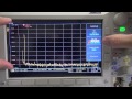 Spectrum Analyzer, Scope and FFT looking at Signals
 3. Divide & Conquer: FFT
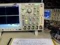 #65: Basics of using FFT on an oscilloscope
 What is a Fourier Series? (Explained by drawing circles) - Smarter Every Day 205
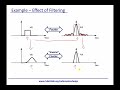 Module 1: Time vs Frequency Domains
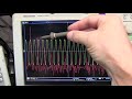 #305: Measuring Total Harmonic Distortion THD using an FFT on an oscilloscope
 Fourier Transform, Fourier Series, and frequency spectrum
 The intuition behind Fourier and Laplace transforms I was never taught in school
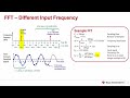 TI Precision Labs – ADCs: Fast Fourier Transforms (FFTs) and Windowing
 FFT in excel for spectral analysis
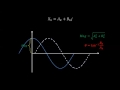 Discrete Fourier Transform - Simple Step by Step
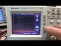 #202: Basics of using FFT on a Tektronix TDS2000 oscilloscope
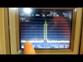 #119: Basics of Resolution Bandwidth and Video Bandwidth in a Spectrum Analyzer (RBW VBW)
 Lecture 1 | The Fourier Transforms and its Applications
 Oscilloscope Tutorial (Basics 101)
![Denoising Data with FFT [Python]](https://i.ytimg.com/vi/s2K1JfNR7Sc/default.jpg) Denoising Data with FFT [Python]
Denoising Data with FFT [Python] The FFT Algorithm - Simple Step by Step
 The Fast Fourier Transform (FFT): Most Ingenious Algorithm Ever?
 But what is a Fourier series? From heat flow to circle drawings | DE4