- Популярные видео
- Авто
- Видео-блоги
- ДТП, аварии
- Для маленьких
- Еда, напитки
- Животные
- Закон и право
- Знаменитости
- Игры
- Искусство
- Комедии
- Красота, мода
- Кулинария, рецепты
- Люди
- Мото
- Музыка
- Мультфильмы
- Наука, технологии
- Новости
- Образование
- Политика
- Праздники
- Приколы
- Природа
- Происшествия
- Путешествия
- Развлечения
- Ржач
- Семья
- Сериалы
- Спорт
- Стиль жизни
- ТВ передачи
- Танцы
- Технологии
- Товары
- Ужасы
- Фильмы
- Шоу-бизнес
- Юмор
Assignment 2.2: Kinematically Challenged using Rhino 7
Analytic Inverse Kinematics for a 3-Link Robotic Arm
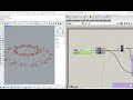
In this assignment, we are tasked with applying kinematic equations to solve for the joint angles of a multi-linked robotic arm. I chose a three-link planar arm because fewer than three links do not fully represent a general manipulator, and after three links in 2D the mathematical process simply repeats. For real industrial applications, inverse kinematics (IK) is the standard approach because it allows the system to compute the required joint angles when a target endpoint is known. I chose to use Rhino 7 with Grasshopper for creating the links and processing the equations.
Inverse kinematics begins with defining a desired endpoint—in this case, point P4—and solving the kinematic chain such that the end of the third segment, P3, coincides with P4 within model precision. The first step is to determine the global end-effector orientation, expressed as φ (phi), using:
ϕ=Atan2(Y,X)
where (X,Y) represents the coordinates of the target relative to the base P0. This gives the global angle from the base to the target.
To isolate the wrist point for solving the first two joints, we back out the position of segment three. We compute the intermediate wrist coordinates:
Xw=X-L3 cos(ϕ)
Yw=Y-L3 sin(ϕ)
Next, we determine θ2—the elbow angle—using the law of cosines:
R^2=X_w^2+Y_w^2
C2=(R^2-L1^2-L2^2)/(2*L1*L2 )
Because numerical rounding can push C2 slightly outside the valid trigonometric range, we apply clamping:
C2=Min(1,Max(-1,C2))
θ2=arccos(C2)
Once θ_2is known, we solve for the shoulder joint angle θ_1:
θ1=Atan2(Yw,Xw) - Atan2(L2 sin(θ2), L1+L2 cos(θ2))
Finally, using the definition of global orientation for serial-chain manipulators:
ϕ=θ1+θ2+θ3
we solve for the third joint:
θ3=ϕ-(θ1+θ2)
This principle extends to any number of joints: each segment’s global angle is the sum of all preceding angles. For an n-degree-of-freedom planar arm:
ϕ=θ1+θ2+θ3+⋯+θn
Thus, inverse kinematics enables a robotic manipulator to determine the configuration of internal joint angles required to reach a user-defined location in space.
________________________________________
References
Lunia, A. (n.d.). Inverse kinematics. In Modeling, motion planning, and control of manipulators and mobile robots. Clemson University Open Textbook. https://opentextbooks.clemson.edu/wangrobotics/chapter/inverse-kinematics/
Robotic arm · RXInfer.jl examples. (n.d.). RXInfer Documentation Project. https://examples.rxinfer.com/categories/advanced_examples/robotic_arm
Видео Assignment 2.2: Kinematically Challenged using Rhino 7 канала Michael
Комментарии отсутствуют
Информация о видео
25 ноября 2025 г. 3:34:29
00:08:54
Другие видео канала