How Tube Amplifiers Work, Part 1: The Power Supply
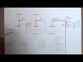
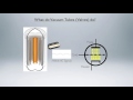
Part 1 of a 2-part video series in which the circuitry of tube amplifiers is explained by breaking down the circuit of a Fender Champ amplifier into sub-units and explaining the design and function of each....in a conversational, rather than purely technical, way. This video covers the Primary (120V 60cps) circuit, the 5V and 6V circuits, the High Voltage circuit, and the general rules that govern the behavior of AC and DC in amp circuits. Additional topics such as transformer winding ratios and the function of vacuum tube (filament) heaters, cathodes, and plates are also explained.
NOTE: There are two ways to look at an amp circuit, based on where the electrons are.....and where they aren't. "Charge" is based on this. Where the electrons ARE is "negative", and where they AREN'T is "positive". In effect, the power supply is an electron pump. It pumps all the electrons out of the circuit and into the chassis, so the circuit (i.e. tube plates) have a positive charge and the chassis is negative. At this point you could say that the circuit has a charge of +325V compared to the chassis at 0V, or that the chassis has a net charge of -325V compared to the circuit at 0V. One or the other. It is the accepted standard, however, to say that the circuit is +325V compared to the chassis, which is at 0V.
My diagram was meant to convey this, but ended up being confusing for many people. Hopefully, the explanation above makes sense. If not, here is an analogy: If you drive 50 miles away from home, there are two ways of describing your position: You are either 50 miles from home, or home is 50 miles from you. One or the other. You can't add the distances and say you are 100 miles apart. Either you or home have to be set at zero distance.
PLEASE NOTE: I have made some changes to this video to update it's accuracy and improve the content. Whenever the notes contradict the narrative, especially during the rectifier portion, please heed the notes.
ALSO: I have since released an updated and much more comprehensive video describing this topic. Here is the link: https://youtu.be/O3Cvhnhv0dM
If you enjoy videos that feature classic vintage tube amps, jukeboxes, weird electro-mechanical devices, and home-built electronics projects, then please subscribe to my channel. You will gain immediate access to 200+ videos, and (if you activate the service) you will be notified each time a new video is posted. You can also become a Patreon patron at: https://www.patreon.com/uncledougsvintageamps or make a PayPal donation to: dldcam@aol.com . Thanks for watching !!!
Link to Part 2: http://youtu.be/901iaPVVzY0
Видео How Tube Amplifiers Work, Part 1: The Power Supply канала Uncle Doug
Показать
Комментарии отсутствуют
Информация о видео
Другие видео канала
 How Tube Amplifiers Work, Part 2: The Pre-Amp and Power Amp
 What do vacuum tubes (valves) do?
 Build Your Own Current Limiter for Protection when Repairing and Testing Electronic Equipment
 Vacuum Tubes: Episode 1 - The Basics and the Diode
 1978 Fender 135W Twin Reverb Kicks Ass.....in more ways than one
 Tube Amp Power Supply Design
 How Vacuum Tubes Work
 What are the differences between Class A, AB, and Class D amplifiers?
 How does an Amplifier Work? (Class-A)
 1964 Fender Blonde Bandmaster: The Noisy Amp That Couldn't Be Fixed
 How To Build a Classic British 18W Tube Guitar Amp Kit
 Tube Amp vs Solid State – What's the Difference?
 How A Tube Works
 Phase Inverters....for the Common Man
 Let's design an build a vacuum tube amplifier from scratch
 How Amplifiers Work: Rectifiers and Filter Capacitors
 1965 Fender Showman.......Back from the dead, but not without an epic struggle
 Building a Tube Amp! Does it produce better audio quality though? EB#47
 Guitar Amp Vacuum Tubes Part 1: Triodes and Tetrodes