How a 3 Phase Pulse Width Modulation (PWM) VFD Inverter Works Simulation
I construct a 3 phase inverter in NI Multisim and demonstrate the operation using oscilloscopes connected to the inverter output. I explain how the IGBT gates are controlled by a PWM sinusoidal controller. Switching frequency and modulation frequency are explained.
Видео How a 3 Phase Pulse Width Modulation (PWM) VFD Inverter Works Simulation канала betechnical.ca
Видео How a 3 Phase Pulse Width Modulation (PWM) VFD Inverter Works Simulation канала betechnical.ca
Показать
Комментарии отсутствуют
Информация о видео
Другие видео канала
 Variable Frequency Drives Explained - VFD Basics IGBT inverter
 VFD Regen Diodes and the Brake Chopper Circuit
 PWM Motor
 Understanding Electromagnetic Radiation! | ICT #5
 Solar Photovoltaic Generation Part 1: Pulse Width Modulation (PWM) DC/AC Inverter
 Duty cycle, frequency and pulse width--an explanation
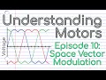 What is Space Vector Modulation? (Episode 10)
 3-phase AC Variable Speed Drive System
 3 Phase AC to DC Rectifier and DC Bus Filtering
 Tesla Model 3's motor - The Brilliant Engineering behind it
 Three Phase PWM Inverter using MATLAB / Simulink
 Power Inverters Explained - How do they work working principle IGBT
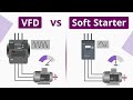 What is the Difference between VFD and Soft Starter?
 How Electric Motors Work - 3 phase AC induction motors ac motor
 Sine Triangle PWM with dead-time in LTspice
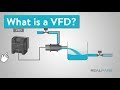 What is a VFD? (Variable Frequency Drive)
 Inverters, How do they work ?
 Single Phase Inverter Simulation Using Insulated Gate Bipolar Transistors IGBTs
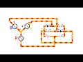 Three Phase Rectifier Animation
 Sine pwm inverter simulink model, SPWM in simulink