Thyristor or SCR Testing Procedure | Procedure to Test the Thyristor with the help of Multimeter
Power Thyristor/Diode Module PK25FG series are designed for various rectifier circuits and power controls. For your circuit application, following internal connections and wide voltage ratings up to 1600V are available and electrically isolated mounting base make your mechanical design easy.
-
IGBT TESTING | How to test an IGBT?
https://youtu.be/IEXfaUYfrDU
-
Procedure to Test the Thyristor with the help of Multimeter:
To test the THYRISTOR, keep the Multimeter into Ohm/Diode meter mode.
Connect the positive output lead of the multimeter to the anode and the negative lead to the cathode.
The multimeter should indicate no continuity.
Touch the gate of the THYRISTOR to the anode.
The multimeter should indicate continuity through the THYRISTOR.
When the gate lead is removed from the anode, conduction may stop or continue depending on whether the multimeter is supplying enough current to keep the device above its holding current level.
If the multimeter indicates continuity through the THYRISTOR before the gate is touched to the anode, it indicates that the THYRISTOR is shorted.
If the multimeter will not indicate continuity through the THYRISTOR after the gate has been touched to the anode, it indicates that the THYRISTOR is open.
#Electrical
#Electronics
#technology
#repairing
#Services
#engineering
#tech
#howto
#testing
#machine
#industry
#maintenances
Видео Thyristor or SCR Testing Procedure | Procedure to Test the Thyristor with the help of Multimeter канала FLOW CHART
-
IGBT TESTING | How to test an IGBT?
https://youtu.be/IEXfaUYfrDU
-
Procedure to Test the Thyristor with the help of Multimeter:
To test the THYRISTOR, keep the Multimeter into Ohm/Diode meter mode.
Connect the positive output lead of the multimeter to the anode and the negative lead to the cathode.
The multimeter should indicate no continuity.
Touch the gate of the THYRISTOR to the anode.
The multimeter should indicate continuity through the THYRISTOR.
When the gate lead is removed from the anode, conduction may stop or continue depending on whether the multimeter is supplying enough current to keep the device above its holding current level.
If the multimeter indicates continuity through the THYRISTOR before the gate is touched to the anode, it indicates that the THYRISTOR is shorted.
If the multimeter will not indicate continuity through the THYRISTOR after the gate has been touched to the anode, it indicates that the THYRISTOR is open.
#Electrical
#Electronics
#technology
#repairing
#Services
#engineering
#tech
#howto
#testing
#machine
#industry
#maintenances
Видео Thyristor or SCR Testing Procedure | Procedure to Test the Thyristor with the help of Multimeter канала FLOW CHART
Показать
Комментарии отсутствуют
Информация о видео
Другие видео канала
 Massive SCR Thyristor - 9000 amps
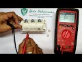 IGBT TESTING | sponsored by Yatin Industronics
 What is a Thyristor? - A Galco TV Tech Tip
 What is inside of an Diode Module | let's breaks it
 SEMIKRON Thyristors test with multimeter | SEMIKRON SKKH42/16E Testing in urdu And hindi
 How to test an IGBT without multimeter
 How to Use a Multimeter for Beginners - How to Measure Voltage, Resistance, Continuity and Amps
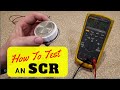 How To Test an SCR
 SCR - How to test using an Analog multimeter only.
 How to test an IGBT with a Multimeter
 What is a THYRISTOR and how it works - PNPN junction
 Como testar tiristores(SCR)de soft-starter. (Erro 77)
 Testing a rectifier
 How to Test a Diode
 testing of thyristor by hot method
 IGBT testing method with multimeter
 Easy way How to test Capacitors, Diodes, Rectifiers on Powersupply using Multimeter
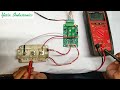 Driver Card Testing with IGBT
 Thyristor In Hindi | Power Electronics | Working & Types Of Thyristor | PART - 1
 How to Identify an PNP or NPN Transistor