11kv Substation Single Line Diagram | One line Diagram | AutoCAD Electricadl | EnggTech
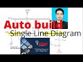
1. The 3-phase, 3-wire 11 kV line is tapped and brought to the gang operating switch installed near the sub-station. The G.O. switch consists of isolators connected in each phase of the 3-phase line.
2. From the G.O. switch, the 11 kV line is brought to the indoor sub-station as underground cable. It is fed to the H.T. side of the transformer (11 kV/400 V) via the 11 kV O.C.B. The transformer steps down the voltage to 400 V, 3-phase, 4-wire.
3. The secondary of transformer supplies to the bus-bars via the main O.C.B. From the bus-bars, 400 V, 3-phase, 4-wire supply is given to the various consumers via 400 V O.C.B. The voltage between any two phases is 400 V and between any phase and neutral it is 230 V. The single phase residential load is connected between any one phase and neutral whereas 3-phase, 400 V motor load is connected across 3-phase lines directly.
4. The CTs are located at suitable places in the sub-station circuit and supply for the metering and indicating instruments and relay circuits.
Видео 11kv Substation Single Line Diagram | One line Diagram | AutoCAD Electricadl | EnggTech канала Engg Tech
Показать
Комментарии отсутствуют
Информация о видео
Другие видео канала
 How to Create one Line diagram using Etap | Auto Build single Line Diagram | Etap | EnggTech
 How to Perform Load Flow Calculation Using Etap | Load Flow | Electrical Power | Engg Tech
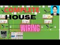 Complete House wiring in 13 minutes | wiring diagram | Engg Tech
 Electrical Plan | Slab Electrical | AutoCAD Electrical | Engg Tech
 Electrical House Plan | Engg Tech
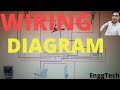 Complete Room electrical wiring diagram | house electrical diagram | Engg Tech
 Single Phase Automatic Changeover Switch for Generator Connection | Automatic switch connection| ATS
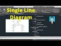 How to Draw one line Diagram in AutoCAD | SLD | single Line Diagram | AutoCAD Electrical | Engg Tech
 Fire Alarm System For commercial building | Fire Alarm Wiring Diagram | Engg Tech
 Floorbox Installation | pop-up floor box| EnggTech
 Best keyboard translator for all languages | Google keyboard | Gborad tutorial | Mobile Keyboard
 How to send Current Location through whatsapp | Share Your current Location
 Best Cad reader app For Mobile phone | Cad Viewer| AWG Reader | Engg Tech