How to Size a Control Valve for Liquid Flow
Learn more about sizing control valves for liquid flow and the steps that go into the process for proper sizing. This video is a step-step procedure for the sizing of control valves for liquid flow using the ISA and IEC procedure. Each of these steps is important and
must be considered during any valve sizing procedure.
1. Specify the variables required to size the valve as follows:
Desired design
Process fluid (water, oil, etc.), and
Appropriate service conditions
q or w, P1, P2 or ΔP, T1, ρ1/ρo, Pv, Pc, and ν
2. Determine the equation constants, N1 and N2.
3. Determine FP, the piping geometry factor, and FLP, the liquid pressure recovery factor adjusted for attached fittings.
4. Determine the pressure drop to use for sizing, ΔPsizing.
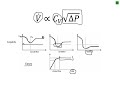
5. Calculate Cv. If this Cv value is not close to the estimate used in step 3, iterate using
this new Cv value and the corresponding FL from the product information.
Additional Resources:
– Control Valve Handbook https://www.emerson.com/documents/automation/control-valve-handbook-en-3661206.pdf
Thanks for watching! Please like, share, and comment on our video and make sure to subscribe to the Fisher Valve & Instruments channel.
Видео How to Size a Control Valve for Liquid Flow канала Fisher Valves & Instruments
must be considered during any valve sizing procedure.
1. Specify the variables required to size the valve as follows:
Desired design
Process fluid (water, oil, etc.), and
Appropriate service conditions
q or w, P1, P2 or ΔP, T1, ρ1/ρo, Pv, Pc, and ν
2. Determine the equation constants, N1 and N2.
3. Determine FP, the piping geometry factor, and FLP, the liquid pressure recovery factor adjusted for attached fittings.
4. Determine the pressure drop to use for sizing, ΔPsizing.
5. Calculate Cv. If this Cv value is not close to the estimate used in step 3, iterate using
this new Cv value and the corresponding FL from the product information.
Additional Resources:
– Control Valve Handbook https://www.emerson.com/documents/automation/control-valve-handbook-en-3661206.pdf
Thanks for watching! Please like, share, and comment on our video and make sure to subscribe to the Fisher Valve & Instruments channel.
Видео How to Size a Control Valve for Liquid Flow канала Fisher Valves & Instruments
Показать
Комментарии отсутствуют
Информация о видео
14 февраля 2019 г. 19:40:50
00:06:22
Другие видео канала
 Control Valve Basics
 Control Valve Sizing Basics: What is Pressure Drop?
 What is CV and How to use CV #Design Tips 5
 How to Size a Control Valve for Compressible Fluid
 Control Valve Selection and Sizing | Building Management System Training | BMS Training 2021
 What is Valve Cavitation? (Animation)
 Control Valve Cv Calculation for Liquids | Simple Science
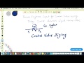 Liquid Control Valve sizing calculation

 Control Valve Selection
 Mounting a Fisher 3582 Positioner on a Control Valve Assembly
 What is control valve flow coefficient Cv? | Learn Instrumentation Engineering
 Pressure Relief Valve Sizing in HYSYS
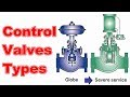 Control Valves Types,Operation and Troubleshooting
 Calibrating a Fisher™ 3582 Positioner - Zero and Span
 How to Read Pump Chart and Select Pump
 Control Valve Sizing for Chemical Engineers
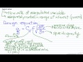 Control Valves
 Shaft Design for INFINITE LIFE and Fatigue Failure in Just Over 10 Minutes!