How to Use a Fluke Multimeter [ Fluke 117 ] - Fluke Multimeter Tutorial
In this video we discuss exactly how to use Fluke multimeter, the Fluke 117. I go through all mode options with simple to follow instructions how to use the multimeter. I then go on to show with a instrument loop diagram how to test for voltage and current.
Welcome back to Instrumentation and control. As a technician you will be frequently working on electronic equipment, you will likely be performing calibration, testing and fault finding on these electrical loops and circuits. In order to understand exactly what is happening within these loops and perform your role as a technician, it is vital you understand how to use a digital process or multi meter in order to measure and simulate loop characteristics such as voltage, current and resistance within these circuits.
In this Video I am going to teach you exactly how to that using a fluke 117 multimeter, which is an extremely common meter used within industry although other meter manufactures use similar symbols and functions so this guide should assist you with most meter types.
Safety
It is important to remember that electricity can be extremely dangerous and in the worst cases cause death. For that reason only work on systems you have the competency to do so and ensure to follow local legislation and guidance and always isolate loops electrically where applicable.
This is a Fluke 117 multi-meter, it is a quality multimeter that has all the basic functionality for taking measurements from an electronic loop. It does not have the functionality to simulate currents that you will need for calibration of input devices and some fault finding, for that type of work you will need a process meter like the Fluke 789, I’ll go over its functionality in the next video.
AC Voltage
Let’s look at this symbol on the mode selector. The “V” stands for Voltage, more specifically this mode is A/C or alternating current voltage, you can tell by looking at the wavy line above the V. This is how the sin wave of AC current would look on a scope or if voltage were graphed against time.
Voltage is the potential difference of energy between two conductors. If these conductors are connected we form a circuit and current flows. A/C voltages you would typically be measuring in industry, depending on your region are single phase at 110-120 or 230-240 and 3 phase 380-415Volts. These voltages are typically found in supply type applications such as equipment power supplies, contactors, cabinet lighting and heaters. They are rarely used in signal applications
For our probe configuration, our black probe would be connected to common and our red probe connected to the V port. Our probes connect between whatever two conductors we are checking voltage between. In single phase applications this is usually between live and neutral and 3 phase applications we would be measuring between the phases or phases to neutral or earth.
Looking at the HZ symbol in yellow on this mode, if we press the yellow function button while measuring an AC voltage we will be able to determine its frequency measured in Hz. A Hert is how many times a second the alternating current voltage cycles, think back to the wave symbol! typical Power supplys in the UK and Europe and most of Asia are 50hz whereas voltages in the US are usually 60hz
Resistance / Continuity
We can use a meter to measure resistance. Resistance is measured in ohms and as its name suggests, it is measurement of the restriction to the flow of electricity. The easier the current flows through a conductor then the lower the resistance. Long low diameter cable will have a high resistance whereas short, high diameter cable will have a low resistance.
In instrumentation the type of things we would be measuring the resistance of are
point to point of signal and power cables
Relay and solenoid coil resistances
Resistance between earth or bonding straps
Testing of fuses
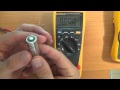
To test for resistance, we need to have our probes connected to the common and ohms symbol. Our probes are red and black, for resistance measurements It does not matter what colour probe we connect to each port on the meter. However, it is good practice to connect the black probe to the common and red probe to the ohm’s connection, this is because when measuring voltage, the polarity is important.
Now you can repeat the test with any part of circuit you wish to measure.
▶▶Check out brilliant T-shirts / Merch at my store: https://www.redbubble.com/people/rudd4y/shop?asc=u&ref=account-nav-dropdown
▶▶Amazon link to Fluke 117 - https://amzn.to/3lNDb1j
▶▶My Website for articles - https://www.instrumentationcontrol.info/
Видео How to Use a Fluke Multimeter [ Fluke 117 ] - Fluke Multimeter Tutorial канала Instrumentation & Control
Welcome back to Instrumentation and control. As a technician you will be frequently working on electronic equipment, you will likely be performing calibration, testing and fault finding on these electrical loops and circuits. In order to understand exactly what is happening within these loops and perform your role as a technician, it is vital you understand how to use a digital process or multi meter in order to measure and simulate loop characteristics such as voltage, current and resistance within these circuits.
In this Video I am going to teach you exactly how to that using a fluke 117 multimeter, which is an extremely common meter used within industry although other meter manufactures use similar symbols and functions so this guide should assist you with most meter types.
Safety
It is important to remember that electricity can be extremely dangerous and in the worst cases cause death. For that reason only work on systems you have the competency to do so and ensure to follow local legislation and guidance and always isolate loops electrically where applicable.
This is a Fluke 117 multi-meter, it is a quality multimeter that has all the basic functionality for taking measurements from an electronic loop. It does not have the functionality to simulate currents that you will need for calibration of input devices and some fault finding, for that type of work you will need a process meter like the Fluke 789, I’ll go over its functionality in the next video.
AC Voltage
Let’s look at this symbol on the mode selector. The “V” stands for Voltage, more specifically this mode is A/C or alternating current voltage, you can tell by looking at the wavy line above the V. This is how the sin wave of AC current would look on a scope or if voltage were graphed against time.
Voltage is the potential difference of energy between two conductors. If these conductors are connected we form a circuit and current flows. A/C voltages you would typically be measuring in industry, depending on your region are single phase at 110-120 or 230-240 and 3 phase 380-415Volts. These voltages are typically found in supply type applications such as equipment power supplies, contactors, cabinet lighting and heaters. They are rarely used in signal applications
For our probe configuration, our black probe would be connected to common and our red probe connected to the V port. Our probes connect between whatever two conductors we are checking voltage between. In single phase applications this is usually between live and neutral and 3 phase applications we would be measuring between the phases or phases to neutral or earth.
Looking at the HZ symbol in yellow on this mode, if we press the yellow function button while measuring an AC voltage we will be able to determine its frequency measured in Hz. A Hert is how many times a second the alternating current voltage cycles, think back to the wave symbol! typical Power supplys in the UK and Europe and most of Asia are 50hz whereas voltages in the US are usually 60hz
Resistance / Continuity
We can use a meter to measure resistance. Resistance is measured in ohms and as its name suggests, it is measurement of the restriction to the flow of electricity. The easier the current flows through a conductor then the lower the resistance. Long low diameter cable will have a high resistance whereas short, high diameter cable will have a low resistance.
In instrumentation the type of things we would be measuring the resistance of are
point to point of signal and power cables
Relay and solenoid coil resistances
Resistance between earth or bonding straps
Testing of fuses
To test for resistance, we need to have our probes connected to the common and ohms symbol. Our probes are red and black, for resistance measurements It does not matter what colour probe we connect to each port on the meter. However, it is good practice to connect the black probe to the common and red probe to the ohm’s connection, this is because when measuring voltage, the polarity is important.
Now you can repeat the test with any part of circuit you wish to measure.
▶▶Check out brilliant T-shirts / Merch at my store: https://www.redbubble.com/people/rudd4y/shop?asc=u&ref=account-nav-dropdown
▶▶Amazon link to Fluke 117 - https://amzn.to/3lNDb1j
▶▶My Website for articles - https://www.instrumentationcontrol.info/
Видео How to Use a Fluke Multimeter [ Fluke 117 ] - Fluke Multimeter Tutorial канала Instrumentation & Control
Показать
Комментарии отсутствуют
Информация о видео
16 октября 2020 г. 3:37:43
00:14:19
Другие видео канала
 How to use a Multimeter for beginners: Part 1 - Voltage measurement / Multimeter tutorial
 Fluke 117 Malaysia vs Fluke China 18B+
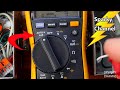 How to Turn Off Ghost Voltages with Dual Impedance (LoZ) Meters
 Adam Savage's Favorite Tools: Best Budget Multimeter!
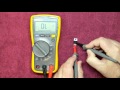 Episode 54 Basic Component Faultfinding with a Multimeter
 Episode 48 Fluke 117 Multimeter Brief Review First Look
 Fluke 177 Training
 Testo 760-2 vs Fluke 117 Multimeter - which is best?
 Multimeter and Electricity Basics | Repair and Replace
 The Best Multimeter Tutorial in The World (How to use & Experiments)
 How to use a Multimeter for beginners: Part 2a - Current measurement
![Instrumentation Calibration - [An Introduction]](https://i.ytimg.com/vi/SamV6zpRNgg/default.jpg) Instrumentation Calibration - [An Introduction]
Instrumentation Calibration - [An Introduction] How to Use a Multimeter
 Electrical Measurement Safety by Fluke
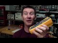 EEVblog #60 - Fluke 117 Multimeter Review and Teardown
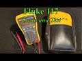 001 Fluke 117 Multimeter
 best fluke multimeters 2021
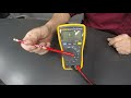 Demonstrating the Fluke 115 Digital Multimeter - Mahwah Campus
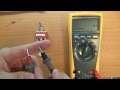 How to use a Multimeter for beginners: Part 3 - Resistance and Continuity
![Pressure Transmitter Workshop Re-range - [HART 475 / Fluke 789 / Druck DPI610 / Foxborough TX]](https://i.ytimg.com/vi/L7T92J7wpzE/default.jpg) Pressure Transmitter Workshop Re-range - [HART 475 / Fluke 789 / Druck DPI610 / Foxborough TX]
Pressure Transmitter Workshop Re-range - [HART 475 / Fluke 789 / Druck DPI610 / Foxborough TX]