- Популярные видео
- Авто
- Видео-блоги
- ДТП, аварии
- Для маленьких
- Еда, напитки
- Животные
- Закон и право
- Знаменитости
- Игры
- Искусство
- Комедии
- Красота, мода
- Кулинария, рецепты
- Люди
- Мото
- Музыка
- Мультфильмы
- Наука, технологии
- Новости
- Образование
- Политика
- Праздники
- Приколы
- Природа
- Происшествия
- Путешествия
- Развлечения
- Ржач
- Семья
- Сериалы
- Спорт
- Стиль жизни
- ТВ передачи
- Танцы
- Технологии
- Товары
- Ужасы
- Фильмы
- Шоу-бизнес
- Юмор
Aruba - Layer 2 Connectivity
✅ LAB OVERVIEW & GOAL
This lab is a basic Layer 2 switching lab where we’ll learn:
How to configure VLANs (Virtual LANs)
The difference between access and trunk ports
How switches forward traffic based on VLAN tags
How devices in the same VLAN can talk to each other, even across different switches
🖼️ STEP 1: Topology Diagram
[PC1]---[SW1]---[SW2]---[PC2]
PC1 = 192.168.10.11 (VLAN 10)
PC2 = 192.168.10.12 (VLAN 10)
PC1 and PC2 are just end devices (like laptops or desktops).
They are connected to two Aruba CX switches.
The switches are connected with a trunk link, which carries VLAN traffic between them.
Both PCs are on the same VLAN (10) and should be able to ping each other.
🔌 WHY THIS MATTERS
Concept What It Means Why It Matters in the Lab
VLAN A way to group ports into separate virtual networks PC1 and PC2 must be in the same VLAN to talk
Access Port Assigned to one VLAN only (for end devices like PCs) Used to connect each PC to its switch
Trunk Port Carries traffic for multiple VLANs between switches Lets VLAN 10 traffic pass between SW1 and SW2
No Routing Needed We're not routing between VLANs (L2 only) Just basic switching, no need for IP on switches
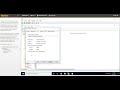
🧱 STEP 2: Setting Up in EVE-NG
You add 2 Aruba OS CX switches (from your image like ArubaOS-CX_10.04) and 2 VPCS nodes.
Connections:
PC1 ↔ SW1 port 1/1/3 (access port)
PC2 ↔ SW2 port 1/1/4 (access port)
SW1 ↔ SW2 via ports 1/1/1 and 1/1/2 (trunk ports)
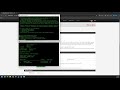
💻 STEP 3: CLI EXPLAINED
🔷 On SW1:
configure terminal # Enter global config mode
hostname SW1 # Name the switch for clarity
vlan 10 # Create VLAN 10
name VLAN10 # Give it a readable name
exit
You now have VLAN 10 created, but you still need to assign ports.
interface 1/1/1 # This is the trunk link to SW2
no routing # This disables Layer 3 (we're doing L2)
no shutdown # Turns the port on
vlan trunk native 1 # VLAN 1 is the untagged default VLAN
vlan trunk allowed 10 # Allow VLAN 10 on the trunk
exit
interface 1/1/3 # Port to PC1
no routing
no shutdown
vlan access 10 # Assign this port to VLAN 10
exit
write memory # Save the config
🔷 On SW2:
Same process, but using its own ports.
configure terminal
hostname SW2
vlan 10
name VLAN10
exit
interface 1/1/2 # Trunk to SW1
no routing
no shutdown
vlan trunk native 1
vlan trunk allowed 10
exit
interface 1/1/4 # Port to PC2
no routing
no shutdown
vlan access 10
exit
write memory
🧑💻 VPCS IP Setup
We are manually giving each PC an IP address on the same network:
PC1:
ip 192.168.10.11 255.255.255.0
PC2:
ip 192.168.10.12 255.255.255.0
They are in the same IP subnet, and on the same VLAN—they should be able to reach each other.
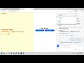
🧪 STEP 4: Testing
On PC1:
ping 192.168.10.12
✅ If the VLAN config is correct:
Switches will forward the traffic properly
PC2 will reply
You will see ping success messages
🧠 WHY THIS LAB IS USEFUL
Skill Learned Real-World Relevance
VLAN configuration Essential for segmenting traffic on enterprise networks
Access vs Trunk ports Used daily by network engineers in switch configs
CLI familiarity Builds comfort with Aruba OS-CX command structure
Testing tools Teaches how to verify with ping
Видео Aruba - Layer 2 Connectivity канала Beaird IT
This lab is a basic Layer 2 switching lab where we’ll learn:
How to configure VLANs (Virtual LANs)
The difference between access and trunk ports
How switches forward traffic based on VLAN tags
How devices in the same VLAN can talk to each other, even across different switches
🖼️ STEP 1: Topology Diagram
[PC1]---[SW1]---[SW2]---[PC2]
PC1 = 192.168.10.11 (VLAN 10)
PC2 = 192.168.10.12 (VLAN 10)
PC1 and PC2 are just end devices (like laptops or desktops).
They are connected to two Aruba CX switches.
The switches are connected with a trunk link, which carries VLAN traffic between them.
Both PCs are on the same VLAN (10) and should be able to ping each other.
🔌 WHY THIS MATTERS
Concept What It Means Why It Matters in the Lab
VLAN A way to group ports into separate virtual networks PC1 and PC2 must be in the same VLAN to talk
Access Port Assigned to one VLAN only (for end devices like PCs) Used to connect each PC to its switch
Trunk Port Carries traffic for multiple VLANs between switches Lets VLAN 10 traffic pass between SW1 and SW2
No Routing Needed We're not routing between VLANs (L2 only) Just basic switching, no need for IP on switches
🧱 STEP 2: Setting Up in EVE-NG
You add 2 Aruba OS CX switches (from your image like ArubaOS-CX_10.04) and 2 VPCS nodes.
Connections:
PC1 ↔ SW1 port 1/1/3 (access port)
PC2 ↔ SW2 port 1/1/4 (access port)
SW1 ↔ SW2 via ports 1/1/1 and 1/1/2 (trunk ports)
💻 STEP 3: CLI EXPLAINED
🔷 On SW1:
configure terminal # Enter global config mode
hostname SW1 # Name the switch for clarity
vlan 10 # Create VLAN 10
name VLAN10 # Give it a readable name
exit
You now have VLAN 10 created, but you still need to assign ports.
interface 1/1/1 # This is the trunk link to SW2
no routing # This disables Layer 3 (we're doing L2)
no shutdown # Turns the port on
vlan trunk native 1 # VLAN 1 is the untagged default VLAN
vlan trunk allowed 10 # Allow VLAN 10 on the trunk
exit
interface 1/1/3 # Port to PC1
no routing
no shutdown
vlan access 10 # Assign this port to VLAN 10
exit
write memory # Save the config
🔷 On SW2:
Same process, but using its own ports.
configure terminal
hostname SW2
vlan 10
name VLAN10
exit
interface 1/1/2 # Trunk to SW1
no routing
no shutdown
vlan trunk native 1
vlan trunk allowed 10
exit
interface 1/1/4 # Port to PC2
no routing
no shutdown
vlan access 10
exit
write memory
🧑💻 VPCS IP Setup
We are manually giving each PC an IP address on the same network:
PC1:
ip 192.168.10.11 255.255.255.0
PC2:
ip 192.168.10.12 255.255.255.0
They are in the same IP subnet, and on the same VLAN—they should be able to reach each other.
🧪 STEP 4: Testing
On PC1:
ping 192.168.10.12
✅ If the VLAN config is correct:
Switches will forward the traffic properly
PC2 will reply
You will see ping success messages
🧠 WHY THIS LAB IS USEFUL
Skill Learned Real-World Relevance
VLAN configuration Essential for segmenting traffic on enterprise networks
Access vs Trunk ports Used daily by network engineers in switch configs
CLI familiarity Builds comfort with Aruba OS-CX command structure
Testing tools Teaches how to verify with ping
Видео Aruba - Layer 2 Connectivity канала Beaird IT
Комментарии отсутствуют
Информация о видео
24 июля 2025 г. 23:59:23
00:10:33
Другие видео канала