Drone Design #1 - Selecting an Airfoil
For more information, visit https://www.airshaper.com
----------------------------------------------------------------------------------------
Drone types
Rotary wings, quadcopters, for example, use the vertical thrust of the propellers to keep the drone in the air. A fixed-wing drone, however, relies on conventional wings to generate the required lift, just like an aeroplane as it travels through the air. In most cases, this setup eliminates any hovering capabilities, but it greatly increases efficiency, giving you much longer flight times.
Fixed wing drones come in many shapes & designs. Some look just like minified aeroplanes, with a propeller at the front, a fuselage in the middle with a long slender wing at both sides and a tail with vertical and horizontal flaps. Blended wings, on the other hand, look very futuristic, with fuselage and wings morphed into a single piece, without any tail at all.
Airfoil basics
Whichever design you go for, you’ll need to choose some kind of wing section, called an airfoil, to generate lift. In more advanced designs, the size or even the shape of this airfoil can change along the width of the wing, but it’s always a good starting point to do some basic hand calculations first.
Let’s start with naming the basic parts of an airfoil. At the front, you have the leading edge, at the back you have the trailing edge. They are connected via the upper surface, also called the suction surface, and the lower surface also called the pressure surface.
The chord is the straight line connecting the leading & trailing edge. The camber line, on the other hand, runs nicely in between the upper and lower surface, showing the centre line of the wing.
The angle of attack is the angle between the chord and the relative wind direction. The relative wind is not only composed of the wind vector but also the velocity of the drone itself.
Lift and drag
Essential to airfoils is how much lift & drag they generate. Lift is the vertical force perpendicular to the relative wind direction. Drag is the horizontal force along the wind direction. These vary in function of the angle of attack. There is a great website called http://www.airfoiltools.com/ that provides you with tons of data on different airfoils. To understand drag & lift curves, let’s illustrate this using a symmetric airfoil, where upper and lower surface are identical. An example is the NACA0012.
At zero angle of attack, the lift is zero as well. There is only drag. As soon as the airfoil rotates its nose into the air, creating a positive angle of attack, it starts generating lift. The bigger the angle of attack, the larger the lift. Beyond a certain critical angle of attack though, the lift will start to decrease again. This operating region beyond the critical angle of attack is called aerodynamic stall and is caused by a separating flow at the suction surface of the airfoil. Trying to pull up too fast during take-off, for example, is a typical scenario in which planes can go into the stall, lose lift and risk crashing.
Another effect of increasing the angle of attack is the increase in aerodynamic drag, which could cancel out the positive effect of lift. To find the sweet spot, we can use the lift-over-drag curve, which plots the ratio of lift over drag in function of the angle of attack. The NACA0012, in this case, reaches its maximum efficiency at an angle of attack of around 8°. At this point, the lift generated by the wing is 80 times bigger than the aerodynamic drag!
This is not the best you can get through. In contrast to symmetric wings, asymmetric wings sacrifice performance at negative angles of attack to generate more lift and less drag at positive angles of attack or even at zero degrees. With airfoil tools, you can easily compare two different airfoils, like the symmetric NACA0012 versus the asymmetric NACA6412. You’ll see that the NACA6412 peaks at a lift over drag ratio of over 140!
As you may have noticed in these curves, lift and drag are expressed as coefficients Cl and Cd, rather than the real lift and drag force. This makes it easier to compare different airfoils, irrespective of their size. The coefficients are calculated by dividing the lift or drag per width of the airfoil by the product of stagnation pressure and the chord length.
For more information, visit:
www.airshaper.com
www.airshaper.com/race-car-aerodynamics
www.facebook.com/AirShaper
www.linkedin.com/company/airshaper
#AirShaper #DroneDesign #AirfoilDesign
Видео Drone Design #1 - Selecting an Airfoil канала AirShaper
Показать
Комментарии отсутствуют
Информация о видео
Другие видео канала
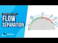 Flow Separation - Boundary layer separation explained
 Aircraft Design Workshop: Fundamentals of Aircraft Aerodynamics
 Engineered Mini Flying Wing
 Drone design #2: 3D Flow Analysis
 Intro To Design Of The Wing
 How ducting a propeller increases efficiency and thrust
 MILVUS Overview_VTOL Fixed Wing UAV
 Understanding Aerodynamic Lift
 Drones | How do they work?
 How to make Quadcopter at Home - Make a Drone
 Calculate Wing Area
 Drone Theory 101: Part 1. The basics, and how an fpv quadcopter functions!
 Heavy Lift Carbon Fiber Drone
 P-51 vs. 109 Drag, The Truth!
 Airfoil-Maker 1: Airfoil Theory
 This Drone is Designed to Save Lives Then Disappear | WIRED
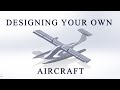 How to Design Your Own Aircraft
 General introduction of X-Swift UAV/Video 2
 Golf Ball Dimples Aerodynamics - How do they work and are they relevant for your design?
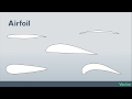 Airfoil Basics