ULTRASONICS NDT Vertical Linearity
Why do we do a Vertical Linearity test? We accept or reject a reflector (crack, non-fusion, etc.) on the amount of sound reflected, so the height of a Pip is the basis of code acceptance. For example lets say that a fictitious code says "If a Pip hits 50% of FSH it is rejectable." Now lets also say that you tested your UT set and it’s not linear. In fact when you have a reading at 40% FSH it is actually 50% FSH. So if your reading from a reflector reads 40%FSH you would accept it when it is actually rejectable. You have to be able to count on your UT set. It has to be accurate.
UT set parameters
SA=Gate A(Green gate)distance in mm to the reflector being measured……SB=Gate B(Blue gate)distance in mm to the reflector being measured……Remember the Gates must cross the PIPS to get a reading
SBA = SB - SA ……A%A= Height of PIP in Gate A …….A%B =Height of Pip in Gate B…….A "PIP " is a tall line on the screen representing a reflecting surface
FOR CALIBRATION
Range=250 mm. Using the 25 mm side of the IIW block adjust the velocity until SBA =225mm. As you can see at 2:24 min the PIP at 10(SB) =250mm . The PIP at 1(SA) = 25 mm. The distance between each PIP should be exactly 25 mm because our cal block is 25mm thick. The 10 PIPS on our screen represents 10 Back Wall reflections. Adding more velocity spreads the PIPs apart, decreasing the velocity compresses the pips together. At this point adjusting your velocity until SBA =250mm-25mm or 225 mm will produce a very exact calibration.
FOR VERTICAL LINEARITY
Using the IIW block three reflecting surfaces are produced.(3 arrows) see 2:54 min. Using any combo of two(2)of the three(3)reflectors manipulate your probe until you get a pip (Ha) @ 60% Full Screen Height (FSH) and another(Hb) @ 30% FSH. See 6:37min. Adding Gain(dB) raise the Ha PIP until it reaches 100% FSH. Hb should then be @ 50% FSH. see 6:47min. Using the Gain Control(dB) take Ha @ 100% FSH down to to Ha @ 10% FSH in 10 % increments. Hb should be one half of Ha at each reading point. Record your readings for Ha and Hb at each 10% increment. If your set is linear your readings should be Ha =100% FSH and Hb =50% FSH.....Ha=90% FSH and Hb =45% FSH..... Ha=80% FSH and Hb=40% FSH.....Ha=70% FSH and Hb=35% FSH.....Ha=60% FSH and Hb =30% FSH..... Ha=50% FSH and Hb =25% FSH..... Ha=40% FSH and Hb =20% FSH.....Ha=30% FSH and Hb =15% FSH.....Ha=20% FSH and Hb =10% FSH and finally Ha=10% FSH and Hb =5% FSH See 6:48 min to 7:40 min and again from 6:54 min to 8:30 min for Ha going from 100% to 10% in 10% increments.
You then Graph your results plotting Ha against Hb. The graph will produce a straight line if your set is linear. I have found that the new digital sets are usually pretty much linear. The old analog sets from 15 to 20 years ago tended to drift in the upper and lower ranges of your UT set.
Видео ULTRASONICS NDT Vertical Linearity канала David Swanson
Показать
Комментарии отсутствуют
Информация о видео
Другие видео канала
 Ultrasonic Testing - Horizontal Linearity (Calibration)
 Ultrasonic Testing - Vertical Linearity (Calibration)
 UT Calibration DAC Curve
 Shear Wave Distance Calibration IIW Block
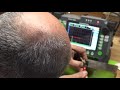 UT Sound Beam Profile Using IOW Block 20dB Drop
 IIW Type 2 Block and Pipe Inspection
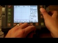 Thin Material Calibration USM 35
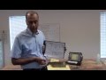 Birring NDT Series, UT of Welds Part 1 of 2 - CALIBRATION
 Ultrasonic Testing
 Birring NDT Series, Ultrasonic Testing # 4, Angle Beam Shear Wave UT as per AWS D1.1
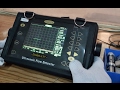 UT calibration and machine settings(Part-1)
 USM 36장비교정 AUTOCALIBRATION
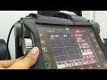 How to : Ultrasonic Testing Normal Probe Calibration
 Calibración del equipo de ultrasonido
 USM 35 Shear Wave Calibration
 Ultrasonic Angle probe calibration, index point and angle checking on USM 35
 Assembling & Testing a Mini 4 Stroke RC Engine
 How to perform a transfer correction
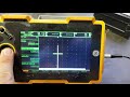 Ut angle probe calibration
 超声波探伤培训