GMT LATHE CHUCK MOUNTING
MOUNTING THE CHUCK
1. Check the location diameter and face of the machine spindle for Radial and Axial Runout using a Dial gauge. Maximum permissible Radial Runout and Axial Runout of the spindle shall not exceed 0.005 mm.
2. Mount the chuck flange on the machine using the clamping screws supplied along with the chuck.
3. Check the flange for true running, ie for Radial and Axial Runout and ensure that these do not exceed 0.005 mm.
4. Connect the draw-tube/draw bar to the cylinder. If the draw-tube/draw bar is to be fitted into the cylinder piston rod, ensure that the piston rod is retracted. If fitted at the intermediate position, the anti-rotation stop pin of the piston may get damaged.
5. Mount the Cylinder Flange on to the rear of the spindle and check the flange for Radial and Axial Runout and ensure that these do not exceed 0.005mm.
6. Mount the cylinder on to the cylinder flange.
7. Connect the pressure ports of the cylinder by hose.
8. Actuate the cylinder at low pressure (4 - 5 kgf/cm2) two or three times, set the piston towards the cover end and switch off the hydraulic power.
9. Remove the cover from the chuck by removing cover clamping screws.
10. Keep the Wedge in fully de-clamped condition (At this position, the jaws will be fully opened).
11. Clean the chuck location diameter and hold the chuck in such a way that the collar just touches the draw-tube end. Tighten the collar on to the draw-tube using the special spanner provided, until the chuck sits properly on the flange face. Align the chuck clamping holes with the tapped holes provided on the chuck flange.
12. Tighten the collar with draw-tube (in case of draw bar, tighten the wedge screw into the drawbar) and chuck clamping screws simultaneously till the chuck location face butts against the flange butting face.
13. True up the periphery of the chuck using a plastic mallet.
14. Ensure there is a gap (approximately 0.5 mm) between the wedge face and body inner face by adjusting wedge screw or wedge collar.
15. Reassemble the cover.
NOTE:
1. Before tightening the chuck flange (Adaptor plate for mounting the chuck) with the Taper nose of the machine spindle, ensure that the clearance between the spindle face and chuck flange butting face is not more than 0.03mm.
2. The flatness of the face of the chuck flange after machining on the machine can have only concavity maximum 0.01mm. Convexity is not permitted. Check with the help of straight edge for blue bearing.
3. Actuate the actuator and check if the jaws move freely over the entire stroke.
Видео GMT LATHE CHUCK MOUNTING канала Guindy Machine Tools Limited
Показать
Комментарии отсутствуют
Информация о видео
6 января 2017 г. 15:26:06
00:04:01
Другие видео канала
 GMT CHUCK CLEANING PROCEDURE
 Chuck Installation Guide
 How to install and Disassembe hydraulic chuck
 How to Properly Cut Lathe Soft Jaws — Part 1: Fundamentals and OD Gripping
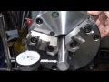 SHOP TIPS #292 Mounting a GATOR Tech-Tru Lathe Chuck tubalcain
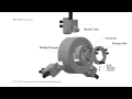 Hydrualic Chuck
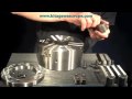 Reassembling a Kitagawa B208 Power Chuck
 Chuck & draw bar service very easy
 Lathe Part Stop Essentials. Do You Know? – Haas Automation Tip of the Day
 How to Replace Drill Chuck.
 Changing Lathe Chucks
 Lathe Chucks
 HYDRAULIC CHUCK CNC LATHE SIZE 8 INCH MERK TAMFOU MADE IN TAIWAN
 Engine Lathe Headstock Tear Down
 Changing a 3 jaw chuck
 GMT CHUCK DISMANTLING PROCEDURE
 Sanou K02-63 63 mm 4 jaw chuck axiality error test on Tesbih Kutusu precission lathe .
 Disassembling a Kitagawa B208 Power Chuck
 CNC선반에서 4각형 가공 Square cnc lathe
 CNC PROGRAMTRAINING- JAWS & CHUCK - HOW TO CLEAN, GREASING, ASSEMBLY MOUNTINGIN HINDIPART 2 | C53