NEW İdea How to Make a Digital Inverter Circuit IC IR2153
NEW İdea How to Make a Digital Inverter Circuit IC IR2153
👉Get a free trial of Altium Designer with 365 and 25% off your purchase :
👉 http://www.altium.com/yt/ZAFERYILDIZ 👈
👉Learn about Altium 365, the electronics product design platform that unites PCB design, MCAD, data management, and teamwork: 👉 https://www.altium.com/altium-365
👉Free search engine for the best quality components from Octopart:
👉https://www.octopart.com
👉Subscribe to JLCPCB with the link below and get your discount discounts
👉https://jlcpcb.com/DTT
👉Circuit Diyagram
👉https://drive.google.com/file/d/1OY42C0O2-cUPGsoX2TXi0tJymx_2u9Mz/view?usp=sharing
Step 1: IR2153 Integrated Circuit
IR2153 is a control integrated circuit that works with a high and low side driver. This IC is ideal for high-efficiency inverters, power supplies, motor drivers, and similar applications. The use of IR2153 IC reduces the complexity of such applications and also provides higher performance.
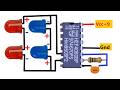
Step 2: Basic Circuit Diagram
The first step in designing a digital inverter circuit is to prepare the basic circuit diagram. The digital inverter circuit designed using the IR2153 IC consists of the following basic elements:
IR2153 IC
N-channel and P-channel MOSFET transistors
DC power supply
Load (such as a motor)
The connections of these elements are shown in the following diagram:
Digital Inverter Circuit Diagram
Step 3: Selection of Circuit Elements
The selection of the IR2153 IC and MOSFET transistors depends on the characteristics of the load you are using. Depending on the voltage and current requirements of the load, the DC power supply is also selected. For example, the output voltage and current of the circuit for a motor should be compatible with the voltage and current requirements of the motor.
Step 4: Circuit Design
After preparing the basic circuit diagram, the circuit design is made. In this design, the connections of the IR2153 IC and MOSFET transistors are determined. Additionally, feedback elements are also added to control the output voltage and current of the circuit. These feedback elements are important for ensuring the stability of the circuit.
Step 5: Prototype and Testing of the Circuit
After the circuit design, a prototype is built and tested. Testing the prototype is important to verify the working principle of the circuit. An oscilloscope and a multimeter can be used to check whether the circuit is working properly and whether the output voltage and current are compatible with the requirements of the load.
I hope this helps!
For sponsoring my video Thank You Altium Designer
#altium
#zaferyildiz
#IR2153
#inverter
Видео NEW İdea How to Make a Digital Inverter Circuit IC IR2153 канала ZAFER YILDIZ
👉Get a free trial of Altium Designer with 365 and 25% off your purchase :
👉 http://www.altium.com/yt/ZAFERYILDIZ 👈
👉Learn about Altium 365, the electronics product design platform that unites PCB design, MCAD, data management, and teamwork: 👉 https://www.altium.com/altium-365
👉Free search engine for the best quality components from Octopart:
👉https://www.octopart.com
👉Subscribe to JLCPCB with the link below and get your discount discounts
👉https://jlcpcb.com/DTT
👉Circuit Diyagram
👉https://drive.google.com/file/d/1OY42C0O2-cUPGsoX2TXi0tJymx_2u9Mz/view?usp=sharing
Step 1: IR2153 Integrated Circuit
IR2153 is a control integrated circuit that works with a high and low side driver. This IC is ideal for high-efficiency inverters, power supplies, motor drivers, and similar applications. The use of IR2153 IC reduces the complexity of such applications and also provides higher performance.
Step 2: Basic Circuit Diagram
The first step in designing a digital inverter circuit is to prepare the basic circuit diagram. The digital inverter circuit designed using the IR2153 IC consists of the following basic elements:
IR2153 IC
N-channel and P-channel MOSFET transistors
DC power supply
Load (such as a motor)
The connections of these elements are shown in the following diagram:
Digital Inverter Circuit Diagram
Step 3: Selection of Circuit Elements
The selection of the IR2153 IC and MOSFET transistors depends on the characteristics of the load you are using. Depending on the voltage and current requirements of the load, the DC power supply is also selected. For example, the output voltage and current of the circuit for a motor should be compatible with the voltage and current requirements of the motor.
Step 4: Circuit Design
After preparing the basic circuit diagram, the circuit design is made. In this design, the connections of the IR2153 IC and MOSFET transistors are determined. Additionally, feedback elements are also added to control the output voltage and current of the circuit. These feedback elements are important for ensuring the stability of the circuit.
Step 5: Prototype and Testing of the Circuit
After the circuit design, a prototype is built and tested. Testing the prototype is important to verify the working principle of the circuit. An oscilloscope and a multimeter can be used to check whether the circuit is working properly and whether the output voltage and current are compatible with the requirements of the load.
I hope this helps!
For sponsoring my video Thank You Altium Designer
#altium
#zaferyildiz
#IR2153
#inverter
Видео NEW İdea How to Make a Digital Inverter Circuit IC IR2153 канала ZAFER YILDIZ
Показать
Комментарии отсутствуют
Информация о видео
Другие видео канала
 Make a Simple Police Flasher Out Of the CD4060
 How To Make A Simple Ultrasonic Humidifier Using A Single Transistor / 2.4 mhz
 How to Make Proximity sensor / Simple diy Long-Range Obstacle Detector
 Top 6 Amazing Projects for Electronics Enthusiasts
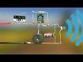 How to make a laser security (burglar) alarm using SCR - 1 KM Range
 This Useful Information / More Than Just a Neon Lamp / Alternative Electronics #Shorts
 how to make a contactless AC Voltage detector Circuit#shorts #zaferyildiz #short #electronics #viral
 How to Build a Proximity Sensor Circuit with Adjustable Range #zaferyildiz #electronics #led
 How To Make An Automatic Torque Control Circuit With 2 Transistors!
 Battery Solution: Stop Swelling and Deterioration - 12V BMS! - For Series Connected Batteries
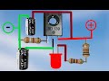 How to make a One Transistor Breathing LED Circuit
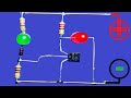 3.7v Lithium Battery Charge Low & Full Indicator Circuit
 How to Make a Simple Battery Protection Circuit
 Say Goodbye to Glass Fuses / Meet with PPTC, Resettable Fuse
 How to Make a Sensitive Fire Alarm Using Mosfets #zaferyildiz #electronics #diy #viral #short
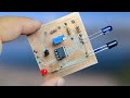 How to Make Proximity sensor / Simple diy Long-Range Obstacle Detector
 Automatic Street Lamp Using Comparator İntegrated - LM393
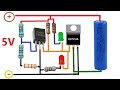 Great idea 3.7 V Battery Charger Circuit / TL431 High Precision Auto Cut-off
 For Those Who Are Tired of Following Battery Voltage - Battery Low Voltage Protection
 How to Make Negative Adjustable Power Supply Using LM337