- Популярные видео
- Авто
- Видео-блоги
- ДТП, аварии
- Для маленьких
- Еда, напитки
- Животные
- Закон и право
- Знаменитости
- Игры
- Искусство
- Комедии
- Красота, мода
- Кулинария, рецепты
- Люди
- Мото
- Музыка
- Мультфильмы
- Наука, технологии
- Новости
- Образование
- Политика
- Праздники
- Приколы
- Природа
- Происшествия
- Путешествия
- Развлечения
- Ржач
- Семья
- Сериалы
- Спорт
- Стиль жизни
- ТВ передачи
- Танцы
- Технологии
- Товары
- Ужасы
- Фильмы
- Шоу-бизнес
- Юмор
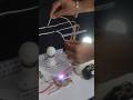
BLDC Temperature controlled fan using Arduino ! BLDC Protection system using Arduino project
#bldcmotor #arduinoprojects #btechprojects
Contact for project -
PROJECTRONICS www.projectronics.in
Buy here - https://projectronics.in/products/bldc-temperature-controlled-fan-using-arduino-with-protection/
Other electrical projects - https://www.youtube.com/watch?v=dKZ8IDoNfk0&list=PLp45IQls-6QfTfBXmmz5IwZWxExT-oJA-
We ll provide 50 pages of pdf and 20 pages pf PPT as a soft copy
What you have to arrange -
1. 24x18 inch any hardsheet - 1
2. Glue gun and stick - 1
3. 100watt Bulb - 1
More projects - www.projectronics.in
Abstarct - The system architecture revolves around an Arduino Uno microcontroller that processes inputs from multiple sensors and controls the AC fan through phase-angle triggering of a TRIAC. The temperature sensor connected to analog pin provides precise temperature readings with 10mV per degree Celsius output, which the Arduino converts to actual temperature values through analog-to-digital conversion. The zero crossing detector circuit, connected to interrupt pin , generates a pulse at every zero crossing of the AC mains waveform (occurring every 10ms for 50Hz systems), which triggers an interrupt service routine that sets a flag for TRIAC firing. Based on the temperature reading, the Arduino calculates the required fan speed using a linear mapping function where temperatures between 20°C and 40°C correspond to fan speeds ranging from 10% to 100%. The calculated delay angle, inversely proportional to desired speed, determines how long after zero crossing the TRIAC receives its gate pulse through the MCT2E optoisolator. The voltage sensor continuously monitors the AC mains voltage with a 0-5V input range mapped to 0-300V actual, triggering an over-voltage fault and activating the buzzer if readings exceed 250V. Similarly, the power sensor on pin A3 monitors consumption with 0-5V corresponding to 0-20W, activating protection if power exceeds 10W. The LCD display, interfaced through pins 2-7, updates every 500ms showing current parameters. During fault conditions, the TRIAC firing is immediately stopped, the buzzer activates for 3 seconds, and fault messages appear on the display until conditions normalize with built-in hysteresis. The system employs volatile variables for interrupt-safe communication and includes debouncing mechanisms for reliable zero-crossing detection, ensuring smooth and accurate fan speed control while maintaining complete electrical isolation between control and power circuits.
We also deals with
- Inhouse project training in school and colleges
- Online class/help for invidual projects
- 1000s of readymade projects
- Customized circuits on request
- Both electronics and art n craft materila, retail and wholeselling sale
Arduino fan speed controller, AC fan regulator using Arduino, temperature based fan speed control, LM35 Arduino project, TRIAC phase control circuit, MCT2E optoisolator tutorial, zero crossing detection Arduino, automatic fan regulator, Arduino home automation projects, AC motor speed control, phase angle control using Arduino, Arduino over voltage protection, current monitoring Arduino, Arduino LCD display projects, DIY fan speed controller, smart fan regulator circuit, Arduino AC dimmer, temperature controlled fan, Arduino protection circuits, embedded systems project, electronics DIY, Arduino tutorial for beginners, AC power control using Arduino, TRIAC triggering circuit, optoisolator isolation, Arduino interrupt example, real time monitoring system, energy saving fan controller, smart home automation, Arduino based projects 2024
Видео BLDC Temperature controlled fan using Arduino ! BLDC Protection system using Arduino project канала PROJECTRONICS
Arduino fan speed controller AC fan regulator using Arduino temperature based fan speed control TRIAC phase control circuit MCT2E optoisolator tutorial zero crossing detection Arduino phase angle control using Arduino Arduino over voltage protection current monitoring Arduino smart fan regulator circuit Arduino AC dimmer Arduino protection circuits embedded systems project electronics DIY TRIAC triggering circuit Arduino interrupt example
Комментарии отсутствуют
Информация о видео
13 февраля 2026 г. 19:29:06
00:08:30
Другие видео канала