- Популярные видео
- Авто
- Видео-блоги
- ДТП, аварии
- Для маленьких
- Еда, напитки
- Животные
- Закон и право
- Знаменитости
- Игры
- Искусство
- Комедии
- Красота, мода
- Кулинария, рецепты
- Люди
- Мото
- Музыка
- Мультфильмы
- Наука, технологии
- Новости
- Образование
- Политика
- Праздники
- Приколы
- Природа
- Происшествия
- Путешествия
- Развлечения
- Ржач
- Семья
- Сериалы
- Спорт
- Стиль жизни
- ТВ передачи
- Танцы
- Технологии
- Товары
- Ужасы
- Фильмы
- Шоу-бизнес
- Юмор
5- Common Collector Amplifier
Ever wonder how to connect a high-impedance source to a low-impedance load without distorting the signal? You need an Emitter Follower! In this electronics lab, we build and test a Common Collector (CC) Amplifier. While it looks like a Common Emitter circuit, the CC has unique properties—specifically, high input impedance, low output impedance, and a voltage gain of unity (Av approx 1). Let’s prove the theory on the workbench!
[What You’ll Learn]
- The Theory: Why it’s called an "Emitter Follower" and how it acts as an impedance transformer/buffer.
- Circuit Setup: Biasing the transistor for Common Collector operation (Rc = 0, output taken from Emitter).
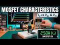
- DC Measurements: Verifying the DC operating point (VB, $VE, VC).
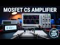
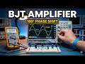
- AC Measurements & Waveforms: Using the oscilloscope to measure Vin vs Vout to prove Av = 1 and observe no phase inversion In-Phase signals).
[Equipment Used]
- NPN Transistor (e.g., 2N2222 or BC547)
- Function Generator
- Oscilloscope
- Digital Multimeter
- Breadboard & Components
#CommonCollector #EmitterFollower #ElectronicsLab #TransistorAmplifier #BufferAmplifier #ElectricalEngineering #Oscilloscope #AnalogDesign
Видео 5- Common Collector Amplifier канала Menna Academy
[What You’ll Learn]
- The Theory: Why it’s called an "Emitter Follower" and how it acts as an impedance transformer/buffer.
- Circuit Setup: Biasing the transistor for Common Collector operation (Rc = 0, output taken from Emitter).
- DC Measurements: Verifying the DC operating point (VB, $VE, VC).
- AC Measurements & Waveforms: Using the oscilloscope to measure Vin vs Vout to prove Av = 1 and observe no phase inversion In-Phase signals).
[Equipment Used]
- NPN Transistor (e.g., 2N2222 or BC547)
- Function Generator
- Oscilloscope
- Digital Multimeter
- Breadboard & Components
#CommonCollector #EmitterFollower #ElectronicsLab #TransistorAmplifier #BufferAmplifier #ElectricalEngineering #Oscilloscope #AnalogDesign
Видео 5- Common Collector Amplifier канала Menna Academy
Комментарии отсутствуют
Информация о видео
28 апреля 2026 г. 11:16:29
00:11:33
Другие видео канала