Electrical Grounding Explained | Basic Concepts
▶ C'mon over to https://realpars.com where you can learn PLC programming faster and easier than you ever thought possible!
=============================
▶ Check out the full blog post over at
https://realpars.com/electrical-grounding
=============================
⌚Timestamps:
00:00 - Intro
00:49 - Why do we a Ground?
01:23 - Earth Ground
02:07 - Graphical Symbol
02:32 - Common Ground
02:58 - 1) Typical example - electronic schematic
04:17 - 2) Typical example - Industrial schematic drawings
04:35 - Ground loops
=============================
In this video, we’re going to discuss the commonly used, but often misunderstood term, Ground.
There are lots of different names for Ground…
There’s Earth, Earth Ground, Neutral, Common Ground, Analog Ground, Digital Ground, and Instrument Ground… just to name a few. And then you have terms like Ground Loops…
Quite often, Ground means different things to different people. For example, Ground to an electrician might mean something different than Ground to electronic engineers.
There are lots of reasons for grounding.
Proper grounding is a critical safety measure in all electrical systems and installations.
We ground the exposed part of electrical equipment so that internal wiring failures don’t raise the voltage potential of these exposed parts to dangerous levels.
Let’s look at some of the different perceptions of the ground.
It’s probably safe to say that Earth and Earth Ground are the same things.
Earth ground is the reference point in an electrical circuit that is a direct and physical connection to the earth. Earth Ground is the ground that you walk on.
Earth Ground is true zero volts. It is the true zero reference for any and every electricity discussion.
You don’t have to go far to see evidence of earth ground.
You might be able to spot a copper rod in the ground with a heavy wire attached to it.
This Earth Ground wire runs to your power panel and ultimately connects to all the Ground terminals of every receptacle in your house.
Notice that we’ve used an electrical symbol for Earth Ground.
The symbols used to indicate ground terminals are found in the International Electrotechnical Commission document IEC 60417 Graphical Symbols for Use on Equipment.
Symbol 5017 is the symbol for Earth Ground.
Every electrical circuit needs to be complete for the current to flow. In many applications, the common ground becomes the return path. For example, your car chassis is a common ground for the return current to the battery’s negative terminal.
Sometimes you’ll see the Earth Ground symbol used incorrectly on electronic schematics. The intention is to symbolize a Common Ground and it may not be connected to Earth Ground.
If ground points are not connected to Earth Ground but are connected to a Common Ground, it would be more appropriate to use the symbol IEC 60417 5020. This symbol suggests the points are connected to a frame or chassis terminal.
This brings up an interesting question…
Are all the components at the common ground potential connected at one point on the frame or chassis, or are they connected to the chassis at multiple locations?
Unfortunately, the schematic does not provide that answer. The schematic does not provide any clue as to physical connections. Industrial schematic drawings will indicate ground points and often provide more detail but physical connection points are still a mystery.
This brings us to a term called Ground Loops.
A Ground Loop is an unwanted electrical current path that can cause havoc in equipment or process control systems by introducing unwanted electrical noise.
These undesired Ground Loops are created when two supposedly connected points are not at the same electrical potential. That’s when Ohm’s Law takes over and creates an electrical current flow between two points.
Ground loops can be avoided if all devices are grounded together at one point. This type of grounded is referred to as Star Point grounding.
Unfortunately, in large industrial plants, multiple-point grounding is the reality, and the possibility of ground loops is high.
With so many connections referenced to the ground within a facility, the chances of needing more than one ground point are great.
=============================
Missed our most recent videos? Watch them here:
https://realpars.com/isa100-wireless-applications
https://realpars.com/hmi-philosophy
https://realpars.com/plcnext-ladder-logic
=============================
To stay up to date with our last videos, make sure to subscribe to this YouTube channel:
http://bit.ly/realpars
=============================
TWEET THIS VIDEO https://ctt.ac/b1fH8
=============================
Follow us on Facebook: https://www.facebook.com/therealpars
Follow us on Twitter: https://twitter.com/realpars
Follow us on LinkedIn https://www.linkedin.com/company/realpars
Follow us on Instagram https://www.instagram.com/realparsdotcom
#RealPars #Electrical #Grounding
Видео Electrical Grounding Explained | Basic Concepts канала RealPars
=============================
▶ Check out the full blog post over at
https://realpars.com/electrical-grounding
=============================
⌚Timestamps:
00:00 - Intro
00:49 - Why do we a Ground?
01:23 - Earth Ground
02:07 - Graphical Symbol
02:32 - Common Ground
02:58 - 1) Typical example - electronic schematic
04:17 - 2) Typical example - Industrial schematic drawings
04:35 - Ground loops
=============================
In this video, we’re going to discuss the commonly used, but often misunderstood term, Ground.
There are lots of different names for Ground…
There’s Earth, Earth Ground, Neutral, Common Ground, Analog Ground, Digital Ground, and Instrument Ground… just to name a few. And then you have terms like Ground Loops…
Quite often, Ground means different things to different people. For example, Ground to an electrician might mean something different than Ground to electronic engineers.
There are lots of reasons for grounding.
Proper grounding is a critical safety measure in all electrical systems and installations.
We ground the exposed part of electrical equipment so that internal wiring failures don’t raise the voltage potential of these exposed parts to dangerous levels.
Let’s look at some of the different perceptions of the ground.
It’s probably safe to say that Earth and Earth Ground are the same things.
Earth ground is the reference point in an electrical circuit that is a direct and physical connection to the earth. Earth Ground is the ground that you walk on.
Earth Ground is true zero volts. It is the true zero reference for any and every electricity discussion.
You don’t have to go far to see evidence of earth ground.
You might be able to spot a copper rod in the ground with a heavy wire attached to it.
This Earth Ground wire runs to your power panel and ultimately connects to all the Ground terminals of every receptacle in your house.
Notice that we’ve used an electrical symbol for Earth Ground.
The symbols used to indicate ground terminals are found in the International Electrotechnical Commission document IEC 60417 Graphical Symbols for Use on Equipment.
Symbol 5017 is the symbol for Earth Ground.
Every electrical circuit needs to be complete for the current to flow. In many applications, the common ground becomes the return path. For example, your car chassis is a common ground for the return current to the battery’s negative terminal.
Sometimes you’ll see the Earth Ground symbol used incorrectly on electronic schematics. The intention is to symbolize a Common Ground and it may not be connected to Earth Ground.
If ground points are not connected to Earth Ground but are connected to a Common Ground, it would be more appropriate to use the symbol IEC 60417 5020. This symbol suggests the points are connected to a frame or chassis terminal.
This brings up an interesting question…
Are all the components at the common ground potential connected at one point on the frame or chassis, or are they connected to the chassis at multiple locations?
Unfortunately, the schematic does not provide that answer. The schematic does not provide any clue as to physical connections. Industrial schematic drawings will indicate ground points and often provide more detail but physical connection points are still a mystery.
This brings us to a term called Ground Loops.
A Ground Loop is an unwanted electrical current path that can cause havoc in equipment or process control systems by introducing unwanted electrical noise.
These undesired Ground Loops are created when two supposedly connected points are not at the same electrical potential. That’s when Ohm’s Law takes over and creates an electrical current flow between two points.
Ground loops can be avoided if all devices are grounded together at one point. This type of grounded is referred to as Star Point grounding.
Unfortunately, in large industrial plants, multiple-point grounding is the reality, and the possibility of ground loops is high.
With so many connections referenced to the ground within a facility, the chances of needing more than one ground point are great.
=============================
Missed our most recent videos? Watch them here:
https://realpars.com/isa100-wireless-applications
https://realpars.com/hmi-philosophy
https://realpars.com/plcnext-ladder-logic
=============================
To stay up to date with our last videos, make sure to subscribe to this YouTube channel:
http://bit.ly/realpars
=============================
TWEET THIS VIDEO https://ctt.ac/b1fH8
=============================
Follow us on Facebook: https://www.facebook.com/therealpars
Follow us on Twitter: https://twitter.com/realpars
Follow us on LinkedIn https://www.linkedin.com/company/realpars
Follow us on Instagram https://www.instagram.com/realparsdotcom
#RealPars #Electrical #Grounding
Видео Electrical Grounding Explained | Basic Concepts канала RealPars
Показать
Комментарии отсутствуют
Информация о видео
Другие видео канала
 Why Neutrals & Grounds are Connected in a Main Panel
 Three-Phase Power Explained
 How to make an earthing / Process of plate Earthing / plate Earthing with PVC pipe / Earth for home
 AEMC® - Understanding Ground Resistance Testing
 MCBs, how do they work?
 Pressure Sensor, Transducer, and Transmitter Explained | Application of Each
 RSD Academy - Lesson 7: What is ground
 The Big Misconception About Electricity
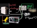 Live wire, neutral & ground (earth wire) - Domestic circuits (part 1) | Physics | Khan Academy
 Why Neutrals and Grounds are Separated in a Sub Panel
 What is a Servo Motor and How it Works?
 How to make Earthing at home. // Earthing connection //
 Power Factor Explained - The basics what is power factor pf
 Grounding and Bonding an Electrical Panel
 Types of Earthing System for Electricity Supplies (UK)
 Pt100 Sensor Explained | Working Principles
 What is Ground? Earth Ground/Earthing
 Earthing Systems vs Electrical Grounding - Difference between Earthing and Grounding
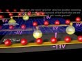 Grounding and Shielding of electric circuits