Mazda Miata Pioneer MSSS1 "Silver Stereo" - Refinishing Faceplate FAIL!
Supplies used for this project include:
Rust-Oleum Satin Nickel Metallic (You can use any color you wish, I chose this out of personal preference) - https://www.amazon.com/Rust-Oleum-249130-Universal-Surface-Metallic/dp/B0042U2QCE/
2K Max Semi-Matte Clearcoat - https://www.amazon.com/Spray-Clear-Coat-Matte-max/dp/B01MXOAWXV/
Waterslide Decal Paper - https://www.amazon.com/Sunnyscopa-Waterslide-Urethane-Standard-sheets/dp/B07FD6MDXH/
Left Pinch Roller (P/N CXA2609) - https://instrumentalparts.com/pinch-roller-l-cxa2609/
Right Pinch Roller (P/N CXA2608) - https://instrumentalparts.com/pinch-roller-r-cxa2608/
Optical Block (CD Laser Assembly) - https://instrumentalparts.com/pick-up-assy-cgy1015/
Test Wiring Harness - https://www.ebay.com/itm/165213795660
--------------------------------------------------------------------------------------------------------------------------------------------------
Instructions for building wiring harness (Documented by fellow MSSS1 enthusiast Tim Allen (no, not THAT Tim Allen!)
Obtain a copy of the service manual, there are several sources on the web - the Pioneer model# to search for is "FH-5071zm" This is needed to identify the pinouts on the harness connector.
Main plug (largest one) (plugs into the top right of the main (upper) unit of the MSSS1 system) [notated as J-01 on page 7 of 93sys.pdf]
1a: BLU/BLK = Radio switched power (active when key is in the ACC or ON position) [Connect to 12v DC + through a 15 amp fuse]
1b: RED/ORG = SYSTEM MUTE [this wire connects directly to 2i of the J-02 harness plug (the medium sized plug)
1c: BLU/RED = BATTERY + (Hot at all times) [Connect to 12v DC + through a 10 amp fuse]
1d: LT GRN/YEL = Power antenna system [this wire gets grounded to activate the power antenna under normal conditions, so connect to 12v DC - ]
1e: RED/BLK = Interior light system: Panel lamp control system (This wire gets power when the car’s interior lights are on [Connect to 12v DC +]
1f: BLU/RED = Illumination OUT [Connects to 2d on J-02, which is Illumination IN]
1h and 1j: Not used here. There is no wire in the harness plug. Some have reported using 1j as a remote amp turn-on, but I cannot confirm this, nor is it necessary for the running of the radio in the car or on the bench.
1k: RED/GRN = FR SP LH+ (Front Speaker Left Hand Positive)
1l: RED/WHT = FR SP LH- (Front Speaker Left Hand Negative)
1m: BLU/YEL = FR SP RH+ (Front Speaker Right Hand Positive)
1n: BLU = FR SP RH- (Front Speaker Right Hand Negative)
----------------------------------------------------
Now we move onto the J-02 harness plug (medium sized one that connects to the bottom unit of the MSSS1 system)
2a: RED/YEL = SPEAKER LH+ (H/R SP) [Headrest Speaker Left Hand Positive]
2b: BLU/ORG = SPEAKER LH- (H/R SP) [Headrest Speaker Left Hand Negative]
2c: BLU/BLK = Radio switched power (active when key is in the ACC or ON position) [Connect to 12v DC + either directly or through a 15 amp fuse]
2d: BLU/RED = Illumination IN [Connects to 1f on J-01, which is Illumination OUT]
2f: RED/BLU = SPEAKER RH+ (H/R SP) [Headrest Speaker Right Hand Positive]
2h: BLU/WHT = SPEAKER RH- (H/R SP) [Headrest Speaker Right Hand Negative]
2i: RED/ORG = SYSTEM MUTE [this wire connects directly to 1b of the J-01 harness plug (the large plug)
2j: GRN/RED = ALC (Automatic Level Control) [Connects to speed sensor (not used for bench testing)]
-----------------------------------------------------------------
The last harness plug (J-03) is the smallest and sends signals to the Bodysonic transducers in the seats. I never bench tested transducers; just made sure the wires were getting voltage.
3a: RED/BLK = BS RH+ (Passenger Side Positive)
3b: RED/WHT = BS RH- (Passenger Side Negative)
3c: BLU/BLK = BS LH+ (Driver Side Positive)
3d: BLU/YEL = BS LH- (Driver Side Negative)
-----------------------------------------------------------------
*NOTES
1a (BLU/BLK), 1c (BLU/RED), 1e (RED/BLK), and 2c (BLU/BLK) are all connected to 12v DC +
I made sure to leave enough slack in a few of the wires for the purpose of connecting the plugs to the radio being tested (See 2nd pic below). I simply joined them further downstream into one positive wire.
I connected 1d (LT GRN/YEL) and a black wire for ground to the ring terminal that attaches to the back of the radio (see 3rd pic below). The other grounds as noted in the above list are then connected downstream to the black wire from the ring terminal, which all terminate into one ground (12v DC -) wire.
The resulting positive and negative wires terminate to a female plug that mates with its respective male plug that has the positive and negative wires used to connect to my DC power supply (see 4th pic below), adding a 15 amp inline fuse for the positive wire (not shown). This step may not be necessary, and I’m not really sure why I made it with the computer Molex connector at the end. I think it was so I can more easily swap out other wiring harnesses I made for other projects.
Видео Mazda Miata Pioneer MSSS1 "Silver Stereo" - Refinishing Faceplate FAIL! канала BBISHOPPCM's World
Показать
Комментарии отсутствуют
Информация о видео
Другие видео канала
 1923 16" GE AOU "Loop Handle" Fan Restoration - Part 1 - Assessment and Disassembly
 Revisiting the HP Compaq NC-8230 - The BEST laptop ever made?
 A Vintage Kitchen Deserves Vintage Lighting
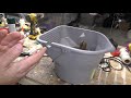 1923 16" GE AOU "Loop Handle" Fan Restoration - Part 3 - Paint Work
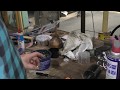 1932 Delco 16" Fan Restoration: Re-assembly, Wiring, and First Run
 Late 1970s TransAudio 1600 Turntable - Does it run?!
 1994 Mazda Miata Front-End Suspension Repairs - Part 2 of 3
 Wiring Adventures with BBISHOPPCM - Installing A New Ceiling Fan In My Breezeway!
 1938 Robbins & Myers 16" "Double Diamond" Pedestal Fan Restoration - Part 2 of 3
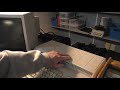 Tandy Personal Deskmate 2.0 - Jack of All Trades, Master of None!
 Tandy 486 PC Restoration - Diagnosing and Fixing Video Issues
 Fun With An Antique Oil Burner - Episode 1
 More of my creations in "The Sims."
 Compaq LTE 5000 Series - Interesting Display Issue
 What's In My Computer Collection? - 8/2/2020
 Mazda Miata Pioneer MSSS1 "Silver Stereo" - Making NEW CD Player Module Mounts from Silicone
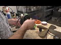 1923 16" GE AOU "Loop Handle" Fan Restoration - Part 2 - Stator Removal & Blade Polishing
 Antique Boice-Crane Spindle Sander - Let's See If It's Even Worth Saving!
 Connecting my Tandy 1000HX to BBS services using WiFi and chatting with random strangers!
 The 1994 Miata projects are FINISHED! Let's HIT THE ROAD!