Interpreting Piping & Instrumentation Diagram (P & ID) in English | Process and Instrumentation
This video talks about what is piping and instrumentation diagram, and how to read P &ID drawing.
If you have any questions about this video, do ask me in the comment box. And please let us know if you need videos on some specific topics related to instrumentation.
- - - - - - - - - - - - - - - - - - - - - - - - - - - - - - - - - -
Video Content:
1. what is P and I D drawing?
- A piping and instrumentation diagram is a visual representation of a process system that includes the piping, vessels, control valves, instrumentation, and other process components and equipment in the system.
- In other words, It is a diagram which shows the interconnection of process equipment, and the instrumentation used to control process.
- The symbols contained in P and ID represent equipment such as actuators, sensors and controllers. Process tools such as valves, instruments, and pipelines are identified by code.
The codes are based on the size, type of fluid being drained, type of pipe connection such as using Bolt or Flange, and the status of the Valve such as Normally Close or Normally Open.
2. How to read P & ID?
- There are the few common piping or connection lines, which is used in P and ID drawing.
- For example, any electrical signal is represented by dotted line.
- And solid line represents straight line pipe.
P & ID Codes Or Symbols:
-In P & ID Codes(symbol), First letter represents parameters that are being controlled or monitored. For Example, it may be Flow, Level, Temperature ,or Pressure.
- Next Letter indicates types of control device being used for measurement. For example, It may be Transmitter, Valve, or Controller.
- Bottom Number is logical numerator. And It is used for identification of equipment.
- Circle with no line indicates that, Level Transmitter number zero zero three is mounted in the field area.
-Logical numerator or Numbered is very useful to identify equipment, when diagram has same equipment more than one.
How to identify instrument location from symbol?
- Circle with no line indicates that, instrument is mounted in the field area.
- And circle with dotted line indicates that, instrument is mounted in control room.
- Lastly, circle with solid line indicates that, instrument is not directly accessible.
- - - - - - - - - - - - - - - - - - - - - - - - - - - - - - - - - -
If you have missed our most recent videos, then watch them here:
1. DP Transmitter Calibration
https://youtu.be/nDGVIH_sMDA
2. Pressure Transmitter Calibration
https://youtu.be/Ck2VYpIbQ5k
3. Closed Tank Level Measurement
https://youtu.be/QJHG4BtTMx8
4. DP Transmitter Wet Leg Calculation
https://youtu.be/im3zumwDC8A
5. Linear mA to Square Root mA Conversion
https://youtu.be/Da-9qHK_E0o
6. Draeger Polytron 8000 Calibration
https://youtu.be/EG5dY3KgaC8
7. How to calibrate MSA Ultima XA/XE Series
https://youtu.be/30GygljDNAM
8. Draeger X-am 2500 calibration
https://youtu.be/OQESuGn6ynY
9. Ashcroft Pressure Switch Calibration
https://youtu.be/Fm7YH72V_Rk
10. What is Fail Safe Condition in Pressure Switch?
https://youtu.be/hp25ZmiuLf0
- - - - - - - - - - - - - - - - - - - - - - - - - - - - - - - - - -
Keep Supporting us.
|| LIKE || COMMENT || SUBSCRIBE ||
- - - - - - - - - - - - - - - - - - - - - - - - - - - - - - - - - -
#P_and_ID #Instrumentation #Instrument_Calibration
#p_&_id_drawing #p&id_symbols
#p&id_autocad #p&id_drawing_tool
#p&id_abbreviations #instrumentation_p&id
#p&id_basics #p&id_explanation
#p&id_valve_symbols
#p&id_drawing_lines
#p&id_definition
#meaning_of_p&id
#read_p&id_sheet
#drawing_for_piping
#p&id_in_visio
#understanding_p&id
#example_p&id
Видео Interpreting Piping & Instrumentation Diagram (P & ID) in English | Process and Instrumentation канала Calibration Academy
Показать
Комментарии отсутствуют
Информация о видео
Другие видео канала
 Ultrasonic Flow Measurement Techniques | Doppler Flow Measurement Vs Transit Time Flow Measurement
 Types Of Modbus Communication Protocols | Protocols working explained
 Types Of Communication Protocols : RS-232 , RS-485 ( Part-1)
 Radar Level Measurement Working Principle : Non contact and guided Wave radar
 Differential Pressure Transmitter Installation for Flow / Level Measurement
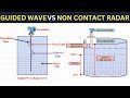 Radar Level Measurement Explained | Guided Wave Radar Vs Non Contact(Pulse)
 List of different types of Control Valve Actuators | Control Valve Actuators Explained
 Radar vs. Ultrasonic Level Measurement: Choose Right Technology for Accurate Results
 List of different type of Control Valve Positioners : Crack Instrumentation Interviews
 Top 7 Challenging & Difficult Instrumentation Interview Questions & Answers
 Control Valves Top 7 Difficult & Tricky Interview Questions and Answers : Instrumentation Interviews
 Control Valve Sizing Calculation Explained | Valve Flow Coefficient(Cv)
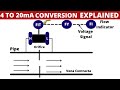 All you need to know about 4- 20 mA Conversion :4-30 mA current loop basics
 Control Valves Top 21 Interview Questions and Answers for Instrumentation Interviews
 Tutorial for DP Transmitter Verification : With and without Square Root Extractor
 Differential Pressure Level Transmitter Tutorial for beginners
 RTD in detail tutorial explaining 2 Wire RTD , 3 Wire RTD and 4 Wire RTD
 Mastering HART: HART Protocol explained for Beginners
 How to perform Analog Output Trim in Differential Pressure Transmitter Calibration
 How to select the right Liner for your Magnetic Flowmeter ? Magmeter Basics
 How to Set Parametere in ABB Flowmeter