Logic Circuits: Timing Diagrams
Demonstrates how to complete timing diagrams of sequential logic circuits using the JK flip-flop. Includes the difference between synchronous and asynchronous inputs and their impact when determining the circuit output.
Видео Logic Circuits: Timing Diagrams канала Jonathan Currie
Видео Logic Circuits: Timing Diagrams канала Jonathan Currie
Показать
Комментарии отсутствуют
Информация о видео
Другие видео канала
 Digital Electronics -- Flip-Flops
 Static Timing Analysis(STA) of Digital circuits- Part 1: Combinational circuits
 megaAVR Microcontrollers: Fast PWM Generation
 D Flip Flops
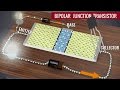 Transistors, How do they work ?
 Asynchronous Sequential Circuit
 Master Slave JK Flip Flop
 moore machine (Timing Diagram)
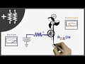 MOSFETs and How to Use Them | AddOhms #11
 4.5 - Timing Hazards & Glitches
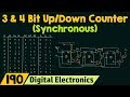 3-Bit & 4-bit Up/Down Synchronous Counter
 Logic Gates and Circuit Simplification Tutorial
 SR Latch Timing Diagram
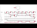 JK Flip Flop Timing Diagrams
 Difference between Latch and Flip Flop
 Timing diagram example
 JK Flip Flop & Master Slave Flip Flop ( Digital Electronics ) ,English:https://youtu.be/TC2EgqJtBpg
 Analysis of a sequential circuit with D and JK flip-flops
 Introduction to Flip Flops.
 Gated SR Latch Examples