- Популярные видео
- Авто
- Видео-блоги
- ДТП, аварии
- Для маленьких
- Еда, напитки
- Животные
- Закон и право
- Знаменитости
- Игры
- Искусство
- Комедии
- Красота, мода
- Кулинария, рецепты
- Люди
- Мото
- Музыка
- Мультфильмы
- Наука, технологии
- Новости
- Образование
- Политика
- Праздники
- Приколы
- Природа
- Происшествия
- Путешествия
- Развлечения
- Ржач
- Семья
- Сериалы
- Спорт
- Стиль жизни
- ТВ передачи
- Танцы
- Технологии
- Товары
- Ужасы
- Фильмы
- Шоу-бизнес
- Юмор
Logic Gate Solved Problem (Wired OR Logic) | Digital Electronics | Quiz # 495
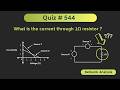
In this video, for the given logic circuit, for how many input combinations, the output becomes 1 is calculated.
Here is the detail of the Quiz:
Question:
In the given logic circuit, the logic gates are implemented using the PMOS transistors. When the transistors are OFF, then the resistor sets the output logic level to ‘0’. The NOR gate implemented using the same method is also shown below. Note that in the given digital circuit, the some nodes are intentionally shorted to implement “wired logic”.
Subject: Digital Electronics
Topic: Logic Gates (Wired OR Connection in logic circuits)
For more videos on Digital Electronics, check this playlist:
https://youtube.com/playlist?list=PLwjK_iyK4LLBC_so3odA64E2MLgIRKafl&si=yh4OFvImWSAJHAhU
#ALLABOUTELECTRONICSQuiz
#digitalelectronics
#logicgates
#wiredOR
The Quiz will be helpful to all the students of science and engineering for preparing for university or competitive exams (GATE, IES, etc.)
Follow me on WhatsApp channel:
https://www.whatsapp.com/channel/0029VaLeZrfAO7RDoKr7je0l
Follow me on Telegram:
t.me/allaboutelectronics1
Follow me on Facebook:
https://www.facebook.com/ALLABOUTELECRONICS/
Follow me on Instagram:
https://www.instagram.com/all_about.electronics/
--------------------------------------------------------------------------------------------------
Music Credit: http://www.bensound.com
Видео Logic Gate Solved Problem (Wired OR Logic) | Digital Electronics | Quiz # 495 канала ALL ABOUT ELECTRONICS - Quiz
gate exam question ece gate ece electronics quiz all about electronics quiz ALL ABOUT ELECTRONICS - Quiz all about electronics - quiz gate exam gate digital electronics digital electronics logic gate solved problems wired OR logic gate wired logic in digital electronics logic gates all about electronics all about electronics digital electronics digital electronics solved problems logic gate wired OR connection PMOS transistors CMOS logic gates
Комментарии отсутствуют
Информация о видео
21 марта 2024 г. 23:55:46
00:09:59
Другие видео канала