RLC Box Filter-Topologies
Now available for sale!
Follow-up video with improvements in the "Deluxe model": https://youtu.be/jruCpnCeRUc
Direct links for purchasing:
Deluxe model: https://www.ak-modul-bus.de/stat/universelle_rlc_box_deluxe_rlc_box2.html
Standard model: https://www.ak-modul-bus.de/stat/rlc_box_standard.html
Before you ask: The little dip you see in the frequency-response curves on the oscilloscope seems to be a resonance-effect from the used 100µH inductor in the prototype. You can see it vanish at the end of the video when I manually change the L and C values in the bandstop-filter.
Видео RLC Box Filter-Topologies канала KainkaLabs
Показать
Комментарии отсутствуют
Информация о видео
Другие видео канала
 Stray-Currents, compensating-currents and ground-loops in Transformers
 The Modul-Lino 1284 - An Arduino-compatible development system Pt.1: Features
![The RIST [Part3]: Hardware and Circuit Diagram](https://i.ytimg.com/vi/WN8oViyDsZc/default.jpg) The RIST [Part3]: Hardware and Circuit Diagram
The RIST [Part3]: Hardware and Circuit Diagram Flickering Tube Filament in an EF98
![The RIST [Part 1] – A programmable, cascadable relay interface](https://i.ytimg.com/vi/YPVvPs74O-g/default.jpg) The RIST [Part 1] – A programmable, cascadable relay interface
The RIST [Part 1] – A programmable, cascadable relay interface Frame-Antenna Contest
![Every maker should have…[Pt.0]...Introduction](https://i.ytimg.com/vi/TpBJEzHWOEs/default.jpg) Every maker should have…[Pt.0]...Introduction
Every maker should have…[Pt.0]...Introduction Vintage Display Technology Pt.11: Numitron & Minitron Displays
 Precision OpAmp Design Pt.2: Input protection & conditioning
![The UNIREL [Part 1] – A universal relay interface](https://i.ytimg.com/vi/knBJ4lj3bus/default.jpg) The UNIREL [Part 1] – A universal relay interface
The UNIREL [Part 1] – A universal relay interface Fish8840 Self-Calibration
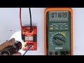 Achieving sub-picoAmp Reverse-Current with OpAmp Protection Diodes
 Hakko FX-951 Clone: Further tests & circuit analysis
 A multi-stage EMI-Filter Pt.2: Effect of the prototype filter with a spectrum-analyzer
![Every maker should have…[Pt.14] Adjustment Screwdrivers](https://i.ytimg.com/vi/KBQe5WMjgMA/default.jpg) Every maker should have…[Pt.14] Adjustment Screwdrivers
Every maker should have…[Pt.14] Adjustment Screwdrivers![The UNIREL [Pt.2]: Schematics, How-It-Works & Tips-for-usage](https://i.ytimg.com/vi/W09LPJTwIAc/default.jpg) The UNIREL [Pt.2]: Schematics, How-It-Works & Tips-for-usage
The UNIREL [Pt.2]: Schematics, How-It-Works & Tips-for-usage A Model of the "Rheinturm Uhr" (Rhine-tower clock)
 Teardown of a Projection-Display
 "Berlin-Uhr" LED replacement
 Precision OpAmp Design Pt.3: Noise-Pickup, Shielding, Grounding, PS-Decoupling
![The RIST [Part2]: Explaining the SYNC-Mode](https://i.ytimg.com/vi/Ay-833eulr4/default.jpg) The RIST [Part2]: Explaining the SYNC-Mode
The RIST [Part2]: Explaining the SYNC-Mode