Exploring UPS system eco modes | Ask Ed & Eaton Insights
Eaton’s critical power expert, Ed Spears, takes a couple minutes to talk about the evolution of eco modes. For more on Eaton's approach to UPS system energy efficiency, visit https://www.eaton.com/us/en-us/products/backup-power-ups-surge-it-power-distribution/backup-power-ups/energy-advantage.html.
TRANSCRIPT:
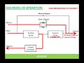
Hi, I'm Ed Spears with Eaton, and today we want to talk about the technical details of how eco mode works in modern UPSs. So on the board here we have a one-line diagram of a traditional double conversion UPS, the rectifier, the inverter, the static switch, and the critical bus output. So, in traditional eco mode, the plan was to basically turn on the static switch and shut off the UPS. The problem was it takes too long to start a UPS from shutdown mode. How do we do that traditionally? Well, you got to close the input contactor, you have to wait for the rectifier to ramp from 0 to 700 volts DC. It's got to do that slowly over about 30 seconds or else you'll stress the capacitors connected in the DC link between the rectifier and the inverter. Then once the 700 volts appears, the inverter can start. Take DC and make AC, but this AC output of the inverter has to be in sync with the critical bus before we can close the output contactor. That's another delay of 10 to 15 seconds to wait for sync. So, close the input contactor, ramp the rectifier for 30 seconds, turn on the inverter, synchronize the inverter, finally close the output contactor. and you have an output from the UPS. Process takes 2 to 3 minutes. It's much much much too long. So, how does it work in a modern eco mode? Well, the static switch will be closed if the incoming power is close to perfect, allowing power to flow directly through from input to output and our output contactor and input contactor remain closed. That gives us two benefits. I don't have to wait for the contactor to close, and I don't have to hope it'll close. A contactor that is closed can't fail to close. It eliminates the mechanical component here, so with closed contactors, I have voltage here and I have voltage here. The rectifier and inverter are suspended, but the inverter is still generating its gate commands for its main power transistors. It's not actually firing those transistors, so it's not using any power, but the gate command signals are already in sync with the output here so I don't have to wait for sync when I flash the inverter on. But, what about this rectifier that has to charge these capacitors over 30 seconds from 0 to 700 volts? How do we do that? Well, if we look at the schematic of the inverter. The inverter’s job is to take DC and create AC. Schematically, it looks like this. Here's positive and negative DC and the inverter transistors create phase A, B, and C (a three-phase AC output), but if I'm not gating those transistors when I'm suspended, the transistors disappear from the circuit. They're open switches. Leaving me with six diodes in a bridge rectifier schematic. This means that the inverter diodes will take the existing AC at this point rectified and create the 700 volts DC that we need to keep the caps charge and to quick start the inverter when necessary. So in eco mode I'll have power through the static switch. If the incoming power becomes disturbed, I can flash on the rectifier and the inverter and I can do that in as little as 2 milliseconds (including turning off the static switch). Is that fast enough for the critical devices that we're supporting here? Well, the guidelines say any transitions should be less than 20 milliseconds. The reality is: the faster, the better. The main reason for having eco mode is saving money, so just as an example, let's take a look at a medium-sized UPS. Here we have 250 kilowatt UPS compared against a legacy UPS that's 93% efficient using an eco mode UPS at 99% and the savings at eleven cents a kilowatt hour are $24,500 per year of operation. Significant savings that will actually repay the cost of the UPS within two to three years. By far the biggest concern with eco mode UPS operation is the observer has trouble accepting that we can in fact transition from static switch operation to double conversion operation in less than two milliseconds. So, we use an oscilloscope trace as proof. Here, we see the input power disrupted coming into the UPS and the output power here at the same point. We do not go to zero volts but continue to produce a three-phase output in the transition time from utility power to inverter power is in fact less than two milliseconds. One of the primary concerns with eco mode UPS operation is: what if I have a disaster like a lightning strike on the input terminals of the UPS? So, this graphic shows how that would look. I have a 6500 volt very narrow spike here on the input of the UPS in eco mode, but the green line here shows only a small voltage aberration at the output of the UPS. An eco mode UPS (a good one) can actually suppress lightning strike style surges. [...]
Видео Exploring UPS system eco modes | Ask Ed & Eaton Insights канала UPSBackup
TRANSCRIPT:
Hi, I'm Ed Spears with Eaton, and today we want to talk about the technical details of how eco mode works in modern UPSs. So on the board here we have a one-line diagram of a traditional double conversion UPS, the rectifier, the inverter, the static switch, and the critical bus output. So, in traditional eco mode, the plan was to basically turn on the static switch and shut off the UPS. The problem was it takes too long to start a UPS from shutdown mode. How do we do that traditionally? Well, you got to close the input contactor, you have to wait for the rectifier to ramp from 0 to 700 volts DC. It's got to do that slowly over about 30 seconds or else you'll stress the capacitors connected in the DC link between the rectifier and the inverter. Then once the 700 volts appears, the inverter can start. Take DC and make AC, but this AC output of the inverter has to be in sync with the critical bus before we can close the output contactor. That's another delay of 10 to 15 seconds to wait for sync. So, close the input contactor, ramp the rectifier for 30 seconds, turn on the inverter, synchronize the inverter, finally close the output contactor. and you have an output from the UPS. Process takes 2 to 3 minutes. It's much much much too long. So, how does it work in a modern eco mode? Well, the static switch will be closed if the incoming power is close to perfect, allowing power to flow directly through from input to output and our output contactor and input contactor remain closed. That gives us two benefits. I don't have to wait for the contactor to close, and I don't have to hope it'll close. A contactor that is closed can't fail to close. It eliminates the mechanical component here, so with closed contactors, I have voltage here and I have voltage here. The rectifier and inverter are suspended, but the inverter is still generating its gate commands for its main power transistors. It's not actually firing those transistors, so it's not using any power, but the gate command signals are already in sync with the output here so I don't have to wait for sync when I flash the inverter on. But, what about this rectifier that has to charge these capacitors over 30 seconds from 0 to 700 volts? How do we do that? Well, if we look at the schematic of the inverter. The inverter’s job is to take DC and create AC. Schematically, it looks like this. Here's positive and negative DC and the inverter transistors create phase A, B, and C (a three-phase AC output), but if I'm not gating those transistors when I'm suspended, the transistors disappear from the circuit. They're open switches. Leaving me with six diodes in a bridge rectifier schematic. This means that the inverter diodes will take the existing AC at this point rectified and create the 700 volts DC that we need to keep the caps charge and to quick start the inverter when necessary. So in eco mode I'll have power through the static switch. If the incoming power becomes disturbed, I can flash on the rectifier and the inverter and I can do that in as little as 2 milliseconds (including turning off the static switch). Is that fast enough for the critical devices that we're supporting here? Well, the guidelines say any transitions should be less than 20 milliseconds. The reality is: the faster, the better. The main reason for having eco mode is saving money, so just as an example, let's take a look at a medium-sized UPS. Here we have 250 kilowatt UPS compared against a legacy UPS that's 93% efficient using an eco mode UPS at 99% and the savings at eleven cents a kilowatt hour are $24,500 per year of operation. Significant savings that will actually repay the cost of the UPS within two to three years. By far the biggest concern with eco mode UPS operation is the observer has trouble accepting that we can in fact transition from static switch operation to double conversion operation in less than two milliseconds. So, we use an oscilloscope trace as proof. Here, we see the input power disrupted coming into the UPS and the output power here at the same point. We do not go to zero volts but continue to produce a three-phase output in the transition time from utility power to inverter power is in fact less than two milliseconds. One of the primary concerns with eco mode UPS operation is: what if I have a disaster like a lightning strike on the input terminals of the UPS? So, this graphic shows how that would look. I have a 6500 volt very narrow spike here on the input of the UPS in eco mode, but the green line here shows only a small voltage aberration at the output of the UPS. An eco mode UPS (a good one) can actually suppress lightning strike style surges. [...]
Видео Exploring UPS system eco modes | Ask Ed & Eaton Insights канала UPSBackup
Показать
Комментарии отсутствуют
Информация о видео
Другие видео канала
 Uninterrupted Power Supply (UPS) Operating modes
 Inverters, How do they work ?
 DIY - 12V Mini UPS
 Why Do We Use AC or DC Power?
 Transistors - The Invention That Changed The World
 UPS EATON 9PX. Todo sobre Transformador PPDM1. PPDM2. Tarjeta de monitoreo.
 Eaton 9155 12 kVA Uninterruptible Power System (UPS)
 GE Critical Power UPS Innovation - RPA Technology
 RV Batteries What You Need To Know.
 What is ECO/UPS Mode in Inverter | Luminous inverter Eco Mode and Ups Mode | Luminous Inverter |
 How Inverters Work - Working principle rectifier
 What is a UPS? (Uninterruptible Power Supply)
 Harrop Eaton E Locker vs ARB Air Locker vs TJM Pro Locker Diff Locker REVIEW | ALLOFFROAD#142
 Static Bypass and redundant for online ups
 Battery Backup Systems
 How to Perform a UPS Transfer in a Critical Data Center
 online UPS vs off Line UPS (block diagram)
 SCR as a Switch
 IEM Power Systems Rotabloc UPS 60Hz HD
 How to Quickly Test UPS Batteries Without the UPS Itself