- Популярные видео
- Авто
- Видео-блоги
- ДТП, аварии
- Для маленьких
- Еда, напитки
- Животные
- Закон и право
- Знаменитости
- Игры
- Искусство
- Комедии
- Красота, мода
- Кулинария, рецепты
- Люди
- Мото
- Музыка
- Мультфильмы
- Наука, технологии
- Новости
- Образование
- Политика
- Праздники
- Приколы
- Природа
- Происшествия
- Путешествия
- Развлечения
- Ржач
- Семья
- Сериалы
- Спорт
- Стиль жизни
- ТВ передачи
- Танцы
- Технологии
- Товары
- Ужасы
- Фильмы
- Шоу-бизнес
- Юмор
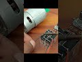
No IC Needed! Flip Flop Bulb Circuit Using Just Transistors #shorts #diyelectronics #shortvideo
🔧 No IC Needed! Flip Flop Bulb Circuit Using Just Transistors – Complete DIY Guide #shorts #diyelectronics #shortvideo
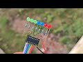
Welcome to our latest DIY electronics tutorial where we show you how to build a Flip Flop Bulb Circuit without using any IC (Integrated Circuit) — just transistors, resistors, capacitors, and a couple of LEDs or bulbs! This is a super fun and simple electronics project that’s perfect for beginners and hobbyists. Whether you're new to electronics or a seasoned maker looking for a creative challenge, this flip-flop bulb circuit is a rewarding hands-on build you’ll love!
👇 Scroll down for full project explanation, components list, working principle, SEO tags, and more!
📌 What You'll Learn in This Video:
How to create a bistable multivibrator (flip flop circuit) using only transistors
Understanding the working principle of capacitor-driven switching
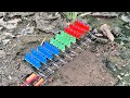
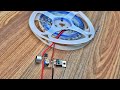
How to flash two bulbs/LEDs alternately with basic components
Tips to modify and scale the circuit for different applications
🎯 Why This Project?
This no-IC flip flop circuit is a great introduction to how transistors and capacitors interact to create timing and oscillation. By eliminating the use of ICs, you’ll gain a deeper understanding of:
Analog electronics
Switching behavior of BJTs (bipolar junction transistors)
RC time constants and how they affect blink rates
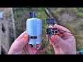
🧰 Components Needed:
Here’s what you’ll need for this flip-flop circuit project:
Component Quantity Notes
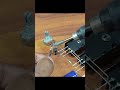
NPN Transistor (e.g., BC547, 2N2222) 2 Acts as electronic switch
Resistors (470Ω – 10kΩ) 4 Two for base, two for collector
Capacitors (10μF – 100μF) 2 Controls timing/blink speed
LEDs or Small Bulbs 2 Output indicators
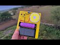
Power Supply (5V – 12V DC) 1 Battery or adapter
Breadboard/Wires As needed For prototyping
🛒 Tip: You can find these components in any basic electronics starter kit or from local electronics stores.
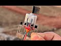
🔄 How the Flip Flop Circuit Works
This circuit is based on a classic design called a bistable multivibrator. Here’s how it works in simple steps:
Initial State: One transistor turns ON, allowing current through one LED/bulb while the other remains OFF.
Capacitor Action: The capacitor connected between the collector of one transistor and the base of the other charges and discharges, triggering the opposite transistor.
Switching: The first transistor switches OFF, and the second turns ON, flipping the LED state.
Loop: This loop continues, making both bulbs flash alternately.
This creates a flip-flop effect with a continuous blinking pattern.
💡 Applications of Flip Flop Circuits
Decorative lighting (e.g., blinking Christmas lights)
Visual indicators for alarms
Educational demonstration of basic transistor operation
Replacement for 555 timer in simple flasher applications
Retro-style electronics toys or gadgets
⚙️ Circuit Diagram Overview
Basic layout:
less
Copy
Edit
Vcc
|
[R1]---+---[Q1 C] [Q2 C]---+---[R2]
| | | |
LED1 | | LED2
| [Q1 E] [Q2 E] |
GND | | GND
Capacitors connect Q1 collector to Q2 base and vice versa.
Note: Ensure correct polarity of LEDs and capacitor orientation (if polarized).
🛠️ Step-by-Step Build Guide
1. Place Transistors on Breadboard
Orient both NPN transistors correctly (Emitter, Base, Collector).
2. Connect LEDs to Collector Terminals
Attach each LED in series with a resistor to each collector.
3. Wire the Resistors from Base to VCC
This keeps a bias voltage on the base, helping with switching.
4. Add Capacitors Between Collector and Opposite Base
Capacitor C1: Collector of Q1 to Base of Q2
Capacitor C2: Collector of Q2 to Base of Q1
5. Power the Circuit
Apply 5V–12V DC power.
Watch the magic as the LEDs blink alternately!
:
🔌 Double-Check:
Transistor orientation (Emitter/Base/Collector)
Capacitor polarity
LED direction
Loose connections
STEM education
School science fairs
Engineering hobbyists
Teaching analog electronics without ICs
Flip Flop Circuit Without IC
Transistor Based Flasher
Bistable Multivibrator DIY
Transistor Circuit Tutorial
LED Blinking Without Timer IC
DIY Flashing LED Circuit
Simple Transistor Projects
Electronics for Beginners
Breadboard LED Projects
flip flop led circuit
simple blnking circuit
electronics mini project
transistor led flasher
alternating led circuit
no ic blinking circuit
diy electronics short
electronics tutorial shorts
how to make led blink with transistor
#FlipFlopCircuit #TransistorOnly #NoICNeeded #DIYElectronics #SimpleElectronics #ElectronicsForBeginners #LEDProjects #CircuitTutorial #ShortsElectronics #BlinkingLED #BreadboardProject #ElectronicsShorts #viralshorts #techshorts #diyelectronics
🔔 Like, Comment & Subscribe!
If you found this video helpful or inspiring:
👉 LIKE the video to support the channel
👉 COMMENT your questions or share your own projects
👉 SUBSCRIBE for more hands-on tutorials, DIY electronics, and creative builds
Видео No IC Needed! Flip Flop Bulb Circuit Using Just Transistors #shorts #diyelectronics #shortvideo канала Sr Electric 2.0
Welcome to our latest DIY electronics tutorial where we show you how to build a Flip Flop Bulb Circuit without using any IC (Integrated Circuit) — just transistors, resistors, capacitors, and a couple of LEDs or bulbs! This is a super fun and simple electronics project that’s perfect for beginners and hobbyists. Whether you're new to electronics or a seasoned maker looking for a creative challenge, this flip-flop bulb circuit is a rewarding hands-on build you’ll love!
👇 Scroll down for full project explanation, components list, working principle, SEO tags, and more!
📌 What You'll Learn in This Video:
How to create a bistable multivibrator (flip flop circuit) using only transistors
Understanding the working principle of capacitor-driven switching
How to flash two bulbs/LEDs alternately with basic components
Tips to modify and scale the circuit for different applications
🎯 Why This Project?
This no-IC flip flop circuit is a great introduction to how transistors and capacitors interact to create timing and oscillation. By eliminating the use of ICs, you’ll gain a deeper understanding of:
Analog electronics
Switching behavior of BJTs (bipolar junction transistors)
RC time constants and how they affect blink rates
🧰 Components Needed:
Here’s what you’ll need for this flip-flop circuit project:
Component Quantity Notes
NPN Transistor (e.g., BC547, 2N2222) 2 Acts as electronic switch
Resistors (470Ω – 10kΩ) 4 Two for base, two for collector
Capacitors (10μF – 100μF) 2 Controls timing/blink speed
LEDs or Small Bulbs 2 Output indicators
Power Supply (5V – 12V DC) 1 Battery or adapter
Breadboard/Wires As needed For prototyping
🛒 Tip: You can find these components in any basic electronics starter kit or from local electronics stores.
🔄 How the Flip Flop Circuit Works
This circuit is based on a classic design called a bistable multivibrator. Here’s how it works in simple steps:
Initial State: One transistor turns ON, allowing current through one LED/bulb while the other remains OFF.
Capacitor Action: The capacitor connected between the collector of one transistor and the base of the other charges and discharges, triggering the opposite transistor.
Switching: The first transistor switches OFF, and the second turns ON, flipping the LED state.
Loop: This loop continues, making both bulbs flash alternately.
This creates a flip-flop effect with a continuous blinking pattern.
💡 Applications of Flip Flop Circuits
Decorative lighting (e.g., blinking Christmas lights)
Visual indicators for alarms
Educational demonstration of basic transistor operation
Replacement for 555 timer in simple flasher applications
Retro-style electronics toys or gadgets
⚙️ Circuit Diagram Overview
Basic layout:
less
Copy
Edit
Vcc
|
[R1]---+---[Q1 C] [Q2 C]---+---[R2]
| | | |
LED1 | | LED2
| [Q1 E] [Q2 E] |
GND | | GND
Capacitors connect Q1 collector to Q2 base and vice versa.
Note: Ensure correct polarity of LEDs and capacitor orientation (if polarized).
🛠️ Step-by-Step Build Guide
1. Place Transistors on Breadboard
Orient both NPN transistors correctly (Emitter, Base, Collector).
2. Connect LEDs to Collector Terminals
Attach each LED in series with a resistor to each collector.
3. Wire the Resistors from Base to VCC
This keeps a bias voltage on the base, helping with switching.
4. Add Capacitors Between Collector and Opposite Base
Capacitor C1: Collector of Q1 to Base of Q2
Capacitor C2: Collector of Q2 to Base of Q1
5. Power the Circuit
Apply 5V–12V DC power.
Watch the magic as the LEDs blink alternately!
:
🔌 Double-Check:
Transistor orientation (Emitter/Base/Collector)
Capacitor polarity
LED direction
Loose connections
STEM education
School science fairs
Engineering hobbyists
Teaching analog electronics without ICs
Flip Flop Circuit Without IC
Transistor Based Flasher
Bistable Multivibrator DIY
Transistor Circuit Tutorial
LED Blinking Without Timer IC
DIY Flashing LED Circuit
Simple Transistor Projects
Electronics for Beginners
Breadboard LED Projects
flip flop led circuit
simple blnking circuit
electronics mini project
transistor led flasher
alternating led circuit
no ic blinking circuit
diy electronics short
electronics tutorial shorts
how to make led blink with transistor
#FlipFlopCircuit #TransistorOnly #NoICNeeded #DIYElectronics #SimpleElectronics #ElectronicsForBeginners #LEDProjects #CircuitTutorial #ShortsElectronics #BlinkingLED #BreadboardProject #ElectronicsShorts #viralshorts #techshorts #diyelectronics
🔔 Like, Comment & Subscribe!
If you found this video helpful or inspiring:
👉 LIKE the video to support the channel
👉 COMMENT your questions or share your own projects
👉 SUBSCRIBE for more hands-on tutorials, DIY electronics, and creative builds
Видео No IC Needed! Flip Flop Bulb Circuit Using Just Transistors #shorts #diyelectronics #shortvideo канала Sr Electric 2.0
flip flop circuit using transistor led chaser circuit blinking led circuit circuit transistor flip flop led flasher circuit using transistor bc547 led chaser circuit using transistor transistor circuits how to make blinking led without using transistor or ic led flasher circuit using bc547 flip flops led circuit using tip 41c flip flop dual led flasher circuit using transistor bc547 flip flop led flasher circuit led circuit led chaser circuit diagram transistors diy
Комментарии отсутствуют
Информация о видео
4 июня 2025 г. 18:31:42
00:01:00
Другие видео канала