Construction of DC machine with Real Parts
Construction Of Dc Generators with real parts
parts
1.yoke or Magnetic Frame
2.Pole
3. inter poles
4.Filed Wingding
5.Field coil
6.copper conductors
7.slot
8.Armature
9.Cores
10.Commutator
11.Brushes
12. Beatings
13. End cover
1.Yoke:
The outer frame of a dc machine is called as yoke. It is made up of cast iron or steel.
It not only provides mechanical strength to the whole assembly but also carries the magnetic flux produced by the field winding.
2. Poles and pole shoes:
Poles are joined to the yoke with the help of bolts or welding. They carry field winding and pole shoes are fastened to them.
Pole shoes serve two purposes;
i) they support field coils and
ii) spread out the flux in air gap uniformly.
3. Field winding:
They are usually made of copper. Field coils are former wound and placed on each pole and are connected in series. They are wound in such a way that, when energized, they form alternate North and South poles.
4.Armature core:
Armature core is the rotor of the machine. It is cylindrical in shape with slots to carry armature winding. The armature is built up of thin laminated circular steel disks for reducing eddy current losses. It may be provided with air ducts for the axial air flow for cooling purposes. Armature is keyed to the shaft.
5.Armature winding:
It is usually a former wound copper coil which rests in armature slots. The armature conductors are insulated from each other and also from the armature core. Armature winding can be wound by one of the two methods;
lap winding or wave winding. Double layer lap or wave windings are generally used. A double layer winding means that each armature slot will carry two different coils.
6.Commutator and brushes:
Physical connection to the armature winding is made through a commutator-brush arrangement. The function of a commutator, in a dc generator, is to collect the current generated in armature conductors. Whereas, in case of a dc motor, commutator helps in providing current to the armature conductors. A commutator consists of a set of copper segments which are insulated from each other. The number of segments is equal to the number of armature coils.
Each segment is connected to an armature coil and the commutator is keyed to the shaft. Brushes are usually made from carbon or graphite
They rest on commutator segments and slide on the segments when the commutator rotates keeping the physical contact to collect or supply the current.
Видео Construction of DC machine with Real Parts канала EEE VIDS
Показать
Комментарии отсутствуют
Информация о видео
Другие видео канала
 How does an Electric Motor work? (DC Motor)
 Construction of a DC Generator | Basic Electrical & Electronics Engineering
 देखिए डीसी जनरेटर कैसे काम करता है| Dc genrator practical in hindi| Dc genrator working | dynamo
![Armature Windings Lap and Wave Windings [Year - 2]](https://i.ytimg.com/vi/wex3ZenASl0/default.jpg) Armature Windings Lap and Wave Windings [Year - 2]
Armature Windings Lap and Wave Windings [Year - 2] DC Machine: Construction And Working Principle (DC Motor & DC Generator)
 Construction and Working of a DC Motor (3D Animation)
 ALTERNATOR PRACTICAL &SYNCHRONOUS MACHINE
 Construction of DC Generator in Tamil
 Construction of DC Machine and Its Components - DC Machines - Basic Electrical Engineering
 Working principle of dc generator with animation | Assembly and working of dc generator | Mruduraj
 Induction motor coil winding setup
 DC MOTOR/DC GENERATOR construction principle and working
 Dc motor experiments | D.C Motor practical | DC motor working | DC Motor explanation | DC MOTOR
 Construction of DC Generator
 DC Motor Testing
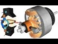 DC Motor, How it works?
 DC Shunt Motor: Construction and Working (Hindi) 💡 Learn all Electric Motors 🎥 Video 1
 DC Motor Armature Rewinding, 5.5-kw from Majeda Electric & Workshop In Bangladesh
 DC Generator working principle of operation in Tamil