Arduino 220VAC Optoisolated Sensor
Green LED = Optocoupler input signal (220 VAC = "1"; 0 VAC = "0")
Red LED = Otpocoupler output signal (220 VAC = "1"; 0 VAC = "0")
The electrical schematic is available here:
http://store.picbg.net/pubpic/17/E7/01757e6267b917e7.jpg
The only difference with my circuit is that on the diagram the output signal is reversed, i.e. you will have logic "0" when there is presence of 220VAC at the input and logic "1" when there is no voltage.
Видео Arduino 220VAC Optoisolated Sensor канала Boyan Aleksandrov
Показать
Комментарии отсутствуют
Информация о видео
Другие видео канала
 Brussels-Deventer-Brussels ride (6/12)
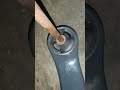 Corolla Verso LCA rear bushing noise
 Autumn ride 2 (Honda SH150i, 2005; SJ4000)
 City ride 2 (Honda SH300i, 2007; SJ4000)
 City ride 1 (Honda SH300i, 2007; SJ4000)
 Corolla Verso LCA rear bushings noise
 Honda SH150i '05
 Rainy ride 2 (Honda SH300i, 2007; SJ4000)
 Brussels to Rotterdam ride (6/8)
 Brussels to Rotterdam ride (3/8)
 Short night ride 1 (Honda SH300, 2007; SJ4000)
 Civic 6 clutch fork greasing
 Brussels ride (2/4)
 Brussels to Rotterdam ride (2/8)
 D15Z6 vacuum leak & fuel pressure check
 Rainy ride 1 (Honda SH300i, 2007; SJ4000)
 October 13, 2021
 Brussels to Rotterdam ride (7/8)
 SingFire SF530 - Powerful Bicycle LED Light
 Accord 7 2.4 catalytic converter stollen