How to Design Wind Turbine Blade Geometry for Optimal Aerodynamic Efficiency
This is part 3 of my series: “How Does a Wind Turbine Work?” In this video I show you how to use the blade element momentum theory, BEM, that we discussed in the last videos, to design an efficient wind turbine rotor.
Topics include:
00:33 Lift equation
00:47 Optimum aerodynamic conditions with constant circulation along the span
01:05 How the local wind speed and angle vary along the length of the blade
01:22 How to change the chord and twist angle along the blade span
01:50 Why designers normally modify the chord distribution to have smaller chords at the root
02:28 The torque equation and why the tip's aerodynamics is more important than the root
02:52 What happens if you use a turbine at a different wind speed than it was designed for
03:46 How variable speed turbines can operate efficiently over a wind range of wind speeds
04:18 What is tip speed ratio (TSR) and why is it important to wind turbine designers?
04:48 Blade solidity
06:07 How to find a starting point in the wind turbine blade design process
07:22 Why are wind turbine blades getting so skinny?
07:54 Reducing wind turbine noise by limiting rotational speed
08:29The different requirements of aerofoils at the root versus tip of the blade
Check out part one and two of my “How Does a Wind Turbine Work?” series where I go through the mechanical engineering and aerodynamic theory needed to understand how a wind turbine works and design a wind turbine blade:
How Much Energy is in the Wind?
https://www.youtube.com/watch?v=7-awFXqisYA&t=7s
How to Calculate Wind Turbine Power Output: Blade Element Momentum Method
https://youtu.be/o6BCnhubbiQ
If you want to follow the derivations I mentioned in this video then check out section 3.7.2 of Burton's "Wind Energy Handbook."
Available to buy from Amazon (affiliate link), or your university library probably has it!
https://amzn.to/32Pb1fh
The optimum aerodynamic design equation at 6:10 has the following parameters:
sigma_r = chord solidity at the radial location (chord length divided by swept circumference at that radial location)
lambda = tip speed ratio (tip speed due to blade rotation (radial location times rotational speed) divided by wind speed)
C_l = local lift coefficient
mu = r/R (radial location divided by radius)
Видео How to Design Wind Turbine Blade Geometry for Optimal Aerodynamic Efficiency канала Engineering with Rosie
Показать
Комментарии отсутствуют
Информация о видео
Другие видео канала

 The Easiest Wind Generator You'll Ever Make
 How to Calculate Wind Turbine Power Output: Blade Element Momentum Method
 Should Wind Turbines Have TWO Blades?
 Understanding Aerodynamic Lift
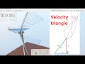 Wind turbine velocity triangle explained with ASHES - the wind turbine simulation software
![[Concepts] How do Wind Turbine Rotors Really Work?](https://i.ytimg.com/vi/9EKPe873L80/default.jpg) [Concepts] How do Wind Turbine Rotors Really Work?
[Concepts] How do Wind Turbine Rotors Really Work? Vertical Axis Wind Turbines - IN 60 SECONDS
 Wind Turbine Blade Design
 The Betz Limit in Wind Turbines
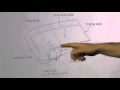 19. Structural design of wind turbine blades
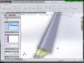 SolidWorks-WindBlade
 WIND BLADE TURBINE Manufacturing Process You Won’t Believe How Are Made – Shocking Production Method
 Wind Turbine Aerodynamics: Stall vs Pitch Regulation
 How to make a Vertical Axis Wind Generator (Is it worth that???)
 The Physics of Windmill Design
 Pvc wind turbine blades
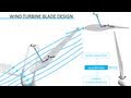 Wind Turbine Design
 Incredible Biggest Wind Turbine Farm Installation Technology. Amazing Giant Factory Machines Working
 Vertical Axis Wind Turbine Aerodynamics and Design