#152 Half Bridge SMPS Converter
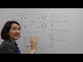
The circuit for half-bridge SMPS (as discussed in the video) It consists of an uncontrolled rectifier, two capacitors C1, C2, two power MOSFETs M1 & M2, one transformer with center-taped secondary side, the capacitors C1 & C2 have equal capacitance, therefore voltage across each is half of the source voltage . When M1 turned on, voltage of C1 appears across transformer primary thus voltage induced in secondary is VS/2,N1.N2 diode D1 is forward biased.
When M2 is turned on, a reverse voltage of C2 appears across transformer primary, voltage induced in secondary winding is -VS/2.N1.N2, therefore diode D2 gets forward biased. This means that transformer primary voltage swings from +ve and -ve
SUBSCRIBE, LIKE SHARE
Thank You
#haseebelect
Youtube https://www.youtube.com/channel/UCamuZ8n1PwdZpzxV32b1l_w
facebook https://web.facebook.com/haseebelect/
Twitter https://twitter.com/haseebelect
Видео #152 Half Bridge SMPS Converter канала Haseeb Electronics
Показать
Комментарии отсутствуют
Информация о видео
Другие видео канала
 How does a Half Bridge converter work? | Half Bridge Converter Working
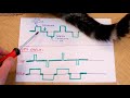 24V 10A 240W power supply - schematic & halfbridge explained
 Half-Bridge Inverter with MOSFET Switches
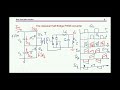 Capacitor “voltage divider” in half bridge converters: An answer to a riddle
 #321 Full Bridge / H-Bridge Isolated Topology / SMPS Circuit Reference Design
 #325 Calculate / Design High Frequency Push Pull/ Half Bridge / Full Bridge Transformer
 #142 FEEDBACK in Switch Mode Power Supply SMPS
![[ e - Learning ] Resonance Half Bridge Converter - Basics of Switching Power Supplies (7)](https://i.ytimg.com/vi/_v_wENwFNLM/default.jpg) [ e - Learning ] Resonance Half Bridge Converter - Basics of Switching Power Supplies (7)
[ e - Learning ] Resonance Half Bridge Converter - Basics of Switching Power Supplies (7)![[ e - Learning ] Full Bridge Converter - Basics of Switching Power Supplies (5)](https://i.ytimg.com/vi/2F9BsGcD1Ok/default.jpg) [ e - Learning ] Full Bridge Converter - Basics of Switching Power Supplies (5)
[ e - Learning ] Full Bridge Converter - Basics of Switching Power Supplies (5)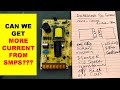 {631} Is It Possible To Modify SMPS (Switch Mode Power Supply) To Increase Output Current
 Half Bridge Smps Converter हिन्दी
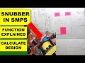 {284} RCD SNUBBER Circuit | What is Snubber Circuit in SMPS and How to Calculate
 Working of a Half Bridge DC to DC Converter
 IR2153 (Ep.1) - Half bridge driver application circuit - #62
 Turn any fixed voltage adapter to variable voltage output (3v - 25v)
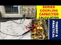 {626} Series Coupling Capacitor Calculation in Half Bridge Push Pull SMPS Circuit Design
 {254} 300 Watt Half Bridge SMPS Using TL494, Circuit Explained, Troubleshooting & Circuit Diagram
 #207 SMPS Output Fluctuating / Low or No regulated output in SMPS
 {592} 300 Watt Half Bridge SMPS Using TL494, Circuit Explained & Troubleshooting & Circuit Diagram