Motorcycle Engine Rebuild the Tear Down
http://www.rrrtoolsolutions.com/articles/motorcycle-transmission-how-and-why-it-works/
We are preparing to do a Motorcycle Engine Rebuild. This is the engine tear down. We speed up the entire process, so you can see the complete engine tear down.
We use our DIY Motorcycle Engine Stand to hold our motorcycle engine during the motorcycle engine rebuilding process.
Hi, Gordon the Tool Guy here. Today we're preparing to do a Motorcycle Engine Rebuild and we're starting off with an Impact Driver by Vessel to remove the Engine Case screws. We'll use the Impact driver to loosen all of the crankcase screws.
This is the left side cover and holds the Stator Coil. The Rotor and Stator generate AC - alternating current (3 Yellow Wires) for our charging and operating current. The Alternating Current runs through the Rectifier which converts it to DC - Direct Current.
Most motorcycles have a separate lighting coil, but on this particular off-road model, lights and the lighting coil are not installed. The Green Wire and small screw are the Neutral Sensor Wire.
Here is another look at the Stator Coil and Rotor.
A Compressor and Air Impact make quick work of removing the Rotor Bolt We need to start the threads of the puller by hand to be sure there is no cross-threading that would permanently damage both the Rotor and the Puller
Again, the Compressor and Air Impact wrench make quick work of removing the Rotor.
With the Rotor removed, we can see that the back side is also a Starter Clutch. The small electric, 12 Volt starter motor turns the small gear, the small gear then turns the larger Starter Gear. When the Starter Gear is driving the Rotor, the Rollers are clamped onto the Crankshaft Gear and Hub.
As soon as the Engine starts, the rotational speed and load releases the Rollers and centrifugal force keeps them pulled out and away from the crankshaft gear.
We remove the Woodruff Key and gears, the starter pinion shaft. Now we're ready to turn this assembly over and disassemble the other side.
Working now on the Right Side, we'll remove the Crankcase cover and expose the Clutch and Oil Pump Using the same Impact screwdriver, we loosen and remove the crankcase screws. We remove the Oil Filter Cover and Filter We remove the Electric Starter
Light tapping around the cover with a plastic mallet and the cover is easily removed
This is the Clutch Assembly - we're looking at the Clutch Pressure Plate, Basket, Friction Disc, and Clutch Plates. We'll start by removing the Springs that are held in-place by these 6mm screws/bolts. I like to remove the tension on the screws/bolts evenly
The Clutch Pressure Plate comes off first, then the friction plates and disc. We'll cover these parts and how they work in a separate video. The locking tabs are opened so that we can remove the large Basket Nut.
Using the Clutch Holding Tool, we can use our Air Impact Wrench to remove our Basket Nut. We can then remove the Inner Clutch Hub and the Clutch Basket itself. The locking tabs are opened and the correct socket chosen
We pull the sparkplug from the cylinder head so that we can rotate the crankshaft and gain access to the Oil Pump screws Using the Air Impact Wrench, the crankshaft and engine balancer shaft nuts are removed The Woodruff Key is removed from the Crankshaft
We pull the Shifter Shaft and the attached Detent, the Centering Spring Guide, and Ratchet Assembly Removing the Oil Pump screws is easier now and we work through the holes in the drive gear We lift the Oil Pump away and remove the displacement rotor
The crankshaft gear is removed.
We position our engine in the Engine Stand so that access to the cylinder head and cylinders easily. This repositioning demonstrates why we like this economical DIY Engine Stand a lot. We remove the Camshaft Sprocket nut then sprocket
The cam chain is pulled down through the cylinder The cam chain tensioner is removed we reposition the engine in our stand to access the head bolts
The head bolts are loosened evenly and carefully so as not to warp the head. Bolts are removed along with their special Copper washers - Copper being a softer metal that provides sealing.
Two 8mm bolts along the side removed The head just lifts off and exposes the head gasket, locating dowels, and the special sealing dowels that carry oil to the top end.
The small 6mm bolts are loosened and removed from the base of the cylinder With the small bolts removed, we can lift the cylinder off the case and piston The rubber cam chain guides pull up too
A quick look at the cylinder bore shows wear and vertical scratches which usually means dirty/contaminated oil and improper lubrication
We reposition the engine in our engine stand so we can access the Center crankcase screws. This is the next step before splitting the case. We remove the cam chain guide
Видео Motorcycle Engine Rebuild the Tear Down канала RRR Tool Solutions 864-710-7964
Показать
Комментарии отсутствуют
Информация о видео
21 ноября 2016 г. 9:41:17
00:07:53
Другие видео канала
 Honda CB250N Engine Restoration | CB250 Hawk Engine Restoration
 1975 Honda TL125 K2 Full Restoration Episode 5
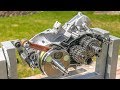 A Problem With My CR250 Engine Build!
 XT 600 Engine assembly part 1
 Starting My Engine Build! | RM250 Rebuild 11
 Yamaha R6 Engine Rebuild Part 1: Bottom End to Piston Install | Partzilla.com
 Complete Motorcycle Build in 15 Minutes - KLR650 Time Lapse
 How a motorcycle transmission works (Animation)
 Understanding Motorcycle Clutch
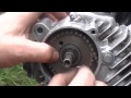 Installing - Rings, Piston, Cylinder & Timing Motorcycle Engine
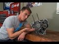 How a Motorcycle Transmission Works | MC GARAGE
 Harley-Davidson Sportster V-Twin Ironhead Engine Rebuild Time-Lapse | Redline Rebuild - S1E6
 BMW Motorcycle Engine Assembly
 XT 600 engine assembly part 2
 Two Stroke Engines Are So Simple!
 How a Motorcycle Transmission Works
 ENGINE OVERHAUL, DISASSEMBLY ,PART 1.
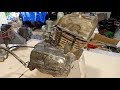 Yamaha125 Engine restoration | Yamaha 125 Two stroke engine rebuild (1979)
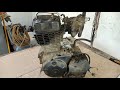 Hero Honda CBZ Xtreme engine restoration (150cc)
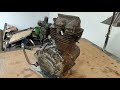 Honda CG125 Engine Restoration