DC Motor Driver Circuit Using Power MOSFETs [PWM Controlled, 30A Half Bridge]
DC Motor Driver Circuit using Power Mosfets [PWM Controlled, 30A Half Bridge]
======================================================
DC motors are everywhere, from hobby applications to robotics and industrial areas. Therefore there is wide usage and request for suitable and powerful DC motor drivers. In this article, we will learn to build one. You can control it using a Microcontroller, an Arduino, a Raspberry Pi or even a standalone PWM generator chip. By using a proper heatsink and cooling methods, this circuit can handle currents up to 30A.
Article: http://bit.ly/2LRBYXH
======================================================
Please support me on Patreon: https://www.patreon.com/myvanitar
======================================================
Check other videos: http://bit.ly/2N9OlPa
======================================================
Welcome!
I’m sure you are curious to know about this circuit and you want to build it. So let me start to explain it first by schematic analysis.
As you can see the heart of this circuit is this MOSFET driver chip. I’ve selected a popular chip which is IR2104. It can drive almost any MOSFET, especially power MOSFETs which are known to have big input capacitance.
That’s actually the main reason why we have to use a MOSFET driver.
The IR2104 is a Half-Bridge driver. The Half-Bridge configuration can deliver more current to the load, besides the load is ground referenced. This is important for some applications.
The capacitors C1 and C2 are used to reduce the noise. I’ve selected minimum 100V rated capacitors because I assumed the worst conditions. 100V is equal with the maximum MOSFET Vds tolerable voltage.
If you are sure that your load voltage is low (For example a 12V DC motor), then you can increase the capacitance and reduce the rated voltages to for example 25V (for instance 1000uf-25V).
There is enough space on the PCB which allows you to use a variety of capacitors. What I used here are 100nF-250V and 220uF-100V.
The last remaining point from this schematic is the input pins of the MOSFET driver. I have pulled down the SD Pin with a 4.7K resistor. Therefore if you apply a steady-state Logic level voltage to the SD pin, you can enable the chip. Otherwise, the chip is disabled and it will not transfer the PWM signal to the MOSFETs. We can say the SD pin acts as a switch.
You will inject your PWM pulse to the IN pin. You can use a Microcontroller, Arduino, Raspberry Pi or another chip such as TL494 to build and control the PWM duty cycle.
I used SamacSys schematic symbols and PCB footprints for the IR2104 driver and IRFP150 MOSFETs. Because at least I will not waste my time to design them from scratch which sometimes accompanies mistakes. All SamacSys services are free of charge.
Don’t forget to follow the description to get more information and see the reference links.
If we briefly look at the IR2104 datasheet, we can see it introduces a few nice features such as input logic compatibility and separate chip and load supply injection capability. It means the power supply for the MOSFET driver and the load’s supply do not need to be identical, but both supplies are certainly ground referenced.
As it is stated, the load supply voltage can reach up to 600V, if the MOSFETs are rated similarly.
The above picture shows the designed PCB layout. The bottom pictures show the assembled circuit board and it is ready for a test. This is just a fast semi-homemade PCB board to test the circuit and to make sure about its true operation.
But you should choose a professional PCB fabrication company because now you are sure the circuit works flawlessly. I suggest you PCBWay.
As it is clear, I have excluded some tracks to not to be covered by the solder mask. The reason is that these tracks might carry a high amount of current, but the PCB track itself cannot tolerate high current flows and will burn out. Therefore you must solder a bare solid copper wire on these uncovered areas to enhance the track’s current transmission capability. For my initial tests, it wasn’t necessary because my selected load consumes less than 3A.
If you want to use the circuit for high current loads, never forget to mount the MOSFETs on a proper heatsink and please make the isolation between each MOSFET and the heatsink using a silicone insulation pad. These pads block the electricity but transfer the heat to the heatsink flawlessly.
#dc_motor_driver
#brushed_motor_driver
#mosfet_driver
#pwm_driver
#motor_driver
Видео DC Motor Driver Circuit Using Power MOSFETs [PWM Controlled, 30A Half Bridge] канала MyVanitar
======================================================
DC motors are everywhere, from hobby applications to robotics and industrial areas. Therefore there is wide usage and request for suitable and powerful DC motor drivers. In this article, we will learn to build one. You can control it using a Microcontroller, an Arduino, a Raspberry Pi or even a standalone PWM generator chip. By using a proper heatsink and cooling methods, this circuit can handle currents up to 30A.
Article: http://bit.ly/2LRBYXH
======================================================
Please support me on Patreon: https://www.patreon.com/myvanitar
======================================================
Check other videos: http://bit.ly/2N9OlPa
======================================================
Welcome!
I’m sure you are curious to know about this circuit and you want to build it. So let me start to explain it first by schematic analysis.
As you can see the heart of this circuit is this MOSFET driver chip. I’ve selected a popular chip which is IR2104. It can drive almost any MOSFET, especially power MOSFETs which are known to have big input capacitance.
That’s actually the main reason why we have to use a MOSFET driver.
The IR2104 is a Half-Bridge driver. The Half-Bridge configuration can deliver more current to the load, besides the load is ground referenced. This is important for some applications.
The capacitors C1 and C2 are used to reduce the noise. I’ve selected minimum 100V rated capacitors because I assumed the worst conditions. 100V is equal with the maximum MOSFET Vds tolerable voltage.
If you are sure that your load voltage is low (For example a 12V DC motor), then you can increase the capacitance and reduce the rated voltages to for example 25V (for instance 1000uf-25V).
There is enough space on the PCB which allows you to use a variety of capacitors. What I used here are 100nF-250V and 220uF-100V.
The last remaining point from this schematic is the input pins of the MOSFET driver. I have pulled down the SD Pin with a 4.7K resistor. Therefore if you apply a steady-state Logic level voltage to the SD pin, you can enable the chip. Otherwise, the chip is disabled and it will not transfer the PWM signal to the MOSFETs. We can say the SD pin acts as a switch.
You will inject your PWM pulse to the IN pin. You can use a Microcontroller, Arduino, Raspberry Pi or another chip such as TL494 to build and control the PWM duty cycle.
I used SamacSys schematic symbols and PCB footprints for the IR2104 driver and IRFP150 MOSFETs. Because at least I will not waste my time to design them from scratch which sometimes accompanies mistakes. All SamacSys services are free of charge.
Don’t forget to follow the description to get more information and see the reference links.
If we briefly look at the IR2104 datasheet, we can see it introduces a few nice features such as input logic compatibility and separate chip and load supply injection capability. It means the power supply for the MOSFET driver and the load’s supply do not need to be identical, but both supplies are certainly ground referenced.
As it is stated, the load supply voltage can reach up to 600V, if the MOSFETs are rated similarly.
The above picture shows the designed PCB layout. The bottom pictures show the assembled circuit board and it is ready for a test. This is just a fast semi-homemade PCB board to test the circuit and to make sure about its true operation.
But you should choose a professional PCB fabrication company because now you are sure the circuit works flawlessly. I suggest you PCBWay.
As it is clear, I have excluded some tracks to not to be covered by the solder mask. The reason is that these tracks might carry a high amount of current, but the PCB track itself cannot tolerate high current flows and will burn out. Therefore you must solder a bare solid copper wire on these uncovered areas to enhance the track’s current transmission capability. For my initial tests, it wasn’t necessary because my selected load consumes less than 3A.
If you want to use the circuit for high current loads, never forget to mount the MOSFETs on a proper heatsink and please make the isolation between each MOSFET and the heatsink using a silicone insulation pad. These pads block the electricity but transfer the heat to the heatsink flawlessly.
#dc_motor_driver
#brushed_motor_driver
#mosfet_driver
#pwm_driver
#motor_driver
Видео DC Motor Driver Circuit Using Power MOSFETs [PWM Controlled, 30A Half Bridge] канала MyVanitar
Показать
Комментарии отсутствуют
Информация о видео
Другие видео канала
 How PWM works | Controlling a DC motor with a homemade circuit
 Designing Power MOSFET Circuits - Circuit Tips and Tricks
 Here is why MOSFET drivers are sometimes essential! || MOSFET Driver Part 1 (Driver, Bootstrapping)
 DC 10-50V 60A 3000W Motor Speed Control PWM Controller module XY-1260
![Switching Power Supply Circuit Using LM2576/LM2596 [Adjustable, Buck Converter, CC-CV]](https://i.ytimg.com/vi/ywFpNdvSC7A/default.jpg) Switching Power Supply Circuit Using LM2576/LM2596 [Adjustable, Buck Converter, CC-CV]
Switching Power Supply Circuit Using LM2576/LM2596 [Adjustable, Buck Converter, CC-CV]![H Bridge DC Motor Driver/Control Circuit [40A PWM, Power MOSFETs]](https://i.ytimg.com/vi/4cxWFa4kg_o/default.jpg) H Bridge DC Motor Driver/Control Circuit [40A PWM, Power MOSFETs]
H Bridge DC Motor Driver/Control Circuit [40A PWM, Power MOSFETs] H Bridge Motor Speed Controller Tutorial
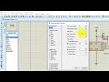 MOSFET Gate Driver Circuit in Proteus | Buck converter | IR2101|
 Control Large Gearmotors with PWM & Arduino
 Higher Voltage MOSFET H-Bridge Motor Circuits
 Complete Guide for 15A 400W MOSFET AOD4184A to control motor or load
 MOSFETs and How to Use Them | AddOhms #11
 Soft Starter Circuits (Inrush Current Limiter) for AC and DC Loads
 How To Make DC Motor Speed Controller
 What is a DC Drive Circuit?
 Build a Power MOSFET H-Bridge for Arduino, PIC
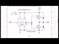 Pt. 2 TC4420-29 MOSFET Drivers Circuit Examples.
 H-bridge DC motor speed control
 Electronic Basics #23: Transistor (MOSFET) as a Switch
 Motor Controllers vs Motor Drivers