- Популярные видео
- Авто
- Видео-блоги
- ДТП, аварии
- Для маленьких
- Еда, напитки
- Животные
- Закон и право
- Знаменитости
- Игры
- Искусство
- Комедии
- Красота, мода
- Кулинария, рецепты
- Люди
- Мото
- Музыка
- Мультфильмы
- Наука, технологии
- Новости
- Образование
- Политика
- Праздники
- Приколы
- Природа
- Происшествия
- Путешествия
- Развлечения
- Ржач
- Семья
- Сериалы
- Спорт
- Стиль жизни
- ТВ передачи
- Танцы
- Технологии
- Товары
- Ужасы
- Фильмы
- Шоу-бизнес
- Юмор
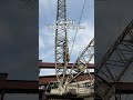
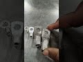
testing earth resistance. #shorts
In this video, we provide a clear, step-by-step demonstration on how to measure soil resistivity and ground electrode resistance using a Digital Earth Tester. Whether you are an electrician, a site engineer, or a student, mastering this test is crucial for ensuring the safety and effectiveness of electrical grounding systems.
📋 What You’ll Learn
We cover the standard Fall-of-Potential method (3-terminal test), which is the most reliable way to verify that your earthing system meets safety standards.
Key Steps Covered:
* Preparation: Safely disconnecting the earth electrode from the main system.
* Probe Placement: How to properly space the Current (C) and Potential (P) spikes (the 5-10 meter rule).
* Connections: Wiring the Red (E), Yellow (P), and Red (C) leads to the tester.
* The Test: Operating the digital meter and interpreting the LCD readings.
* Validation: Understanding what a "good" resistance reading looks like based on local regulations (e.g., 5 ohms for most residential setups).
🛠️ Equipment Used
* Digital Earth Resistance Tester
* Two auxiliary ground spikes
* Three sets of color-coded test leads
* Hammer/Mallet for spike insertion
⚠️ Safety First
Always ensure the system is de-energized before disconnecting any earth bonds. Earth resistance testing should be performed during dry weather for the most accurate "worst-case" results.
Found this tutorial helpful?
👍 Like the video
🔔 Subscribe for more electrical testing guides
💬 Comment below if you have questions about specific meter readings!
#ElectricalEngineering
#EarthTesting
#GroundingSystem
#SafetyFirst
#ElectricianTips
#EarthingResistance
#technology
Видео testing earth resistance. #shorts канала ishraq
Комментарии отсутствуют
Информация о видео
31 декабря 2025 г. 21:41:53
00:01:01
Другие видео канала