
- Популярные видео
- Авто
- Видео-блоги
- ДТП, аварии
- Для маленьких
- Еда, напитки
- Животные
- Закон и право
- Знаменитости
- Игры
- Искусство
- Комедии
- Красота, мода
- Кулинария, рецепты
- Люди
- Мото
- Музыка
- Мультфильмы
- Наука, технологии
- Новости
- Образование
- Политика
- Праздники
- Приколы
- Природа
- Происшествия
- Путешествия
- Развлечения
- Ржач
- Семья
- Сериалы
- Спорт
- Стиль жизни
- ТВ передачи
- Танцы
- Технологии
- Товары
- Ужасы
- Фильмы
- Шоу-бизнес
- Юмор
Relay #driver #circuit with #optocoupler #isolation
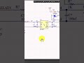
This #circuit is a relay #driver with galvanic #isolation, #designed to safely control an AC load using a low-#voltage #digital signal, such as a #microcontroller GPIO pin.
On the input side, the control signal labeled RELAY4 drives the LED of the PC817 #optocoupler through a 1 kΩ current-limiting resistor. When the input signal is HIGH, current flows through the internal #led of the optocoupler, turning on its internal phototransistor. A 100 nF #capacitor is added to reduce noise and suppress fast transients at the input.
The #key advantage of using the PC817 optocoupler is #electrical isolation. This means the control #logic (microcontroller side) is completely isolated from the high-voltage relay and AC load, improving safety and reducing noise coupling.
On the output side of the optocoupler, the phototransistor drives the relay coil using a 12 V supply. A 470 Ω resistor limits the base/collector current to ensure stable operation. Another 100 nF capacitor helps filter #switching #noise when the relay is energized.
The relay coil is protected by a flyback #diode (1N4148) connected across the coil. This diode suppresses high-voltage spikes generated when the relay is turned off, protecting the optocoupler and other components from damage. Additionally, a 1N4007 diode is used for reverse-polarity or supply protection.
The relay contacts on the right side switch an AC load (AC-F). When the relay coil is energized, the normally-open (NO) contact closes, allowing AC #power to flow to the load.
#stm32 #video #electronics #altiumdesigner #altium
Видео Relay #driver #circuit with #optocoupler #isolation канала mahdi fakher
On the input side, the control signal labeled RELAY4 drives the LED of the PC817 #optocoupler through a 1 kΩ current-limiting resistor. When the input signal is HIGH, current flows through the internal #led of the optocoupler, turning on its internal phototransistor. A 100 nF #capacitor is added to reduce noise and suppress fast transients at the input.
The #key advantage of using the PC817 optocoupler is #electrical isolation. This means the control #logic (microcontroller side) is completely isolated from the high-voltage relay and AC load, improving safety and reducing noise coupling.
On the output side of the optocoupler, the phototransistor drives the relay coil using a 12 V supply. A 470 Ω resistor limits the base/collector current to ensure stable operation. Another 100 nF capacitor helps filter #switching #noise when the relay is energized.
The relay coil is protected by a flyback #diode (1N4148) connected across the coil. This diode suppresses high-voltage spikes generated when the relay is turned off, protecting the optocoupler and other components from damage. Additionally, a 1N4007 diode is used for reverse-polarity or supply protection.
The relay contacts on the right side switch an AC load (AC-F). When the relay coil is energized, the normally-open (NO) contact closes, allowing AC #power to flow to the load.
#stm32 #video #electronics #altiumdesigner #altium
Видео Relay #driver #circuit with #optocoupler #isolation канала mahdi fakher
Комментарии отсутствуют
Информация о видео
8 января 2026 г. 1:13:26
00:02:53
Другие видео канала
 اگر میخواهید پروژههای حرفهایتری طراحی کنید، شناخت این سه پروتکل ضروری است.
 عملگر ساده که جای if استفاده میشه
 Why do we use a Decoupling Capacitor?
 بیا یک مدار ساده pwm یاد بگیر
 ترکهای RF در طراحی PCB
 Electronics lovers #shortvideo #shorts #short #youtubeshorts #youtubeshort #electronic
 #کلید تاچ خودمون بسازیم
 اگر میخواید مدارهای خودتون رو با تغذیه پایدار و کم نویز بسازید، این ویدیو رو از دست ندید!
 چطور باید یک FPGA یا STM32 را با JTAG پروگرام کنیم؟
 Layer stack-up
 با اینکار از اسیلاتور بهتر استفاده کن
 برای هماهنگ کردن طول ترک های سیگنال چه کنیم؟
 آموزش #الکترونیک از #آلتیوم تا #fpga نحوه راه اندازی #میکرو Avr و #stm32. #shortvideo #short
 اتصال رله مکانیکی به #میکرو با روش ایزوله
 داده شمارشی چه کمکی توی کد به ما میکنه؟(enum)
 راز درست کار کردن آنالوگ مدار
 ترک ها در PCB منابع تغذیه
 نکته مهم توی طراحی برد LED
 HOW CAN WE GENERATE A CLOCK?
 CPLD-FPGA
 Why do we use coupling capacitor & oscillator ?
