LED Chaser Circuit with 555 timer
Hello Guys today in this video I will show you How to make LED Chaser Circuit With Using 555 timer
Visit my Website for Buying Links & more Information.
https://www.revealnew.com/
Instructables: https://www.instructables.com/id/Simple-Audio-Amplifier-1/
Subscribe Here: https://www.youtube.com/channel/UCJoXoKcfAo4j9XWDlxCWMyg?sub_confirmation=1
Needed Components Online Link-
1. 555 Timer: https://amzn.to/2BXyAF4
2. Soldering Iron: https://amzn.to/2t5A5wm
3. PCB Board: https://amzn.to/2DECdRA
4. 9v Battery: https://amzn.to/2OXxBYY
5.Female Header: https://amzn.to/2S8U0o4
6. Heat Shrink Tube: https://amzn.to/2yiXJKJ
7. LED: https://amzn.to/2TF1WPz
8. Multi-Color LED: https://amzn.to/2SedJD3
**Note: Use Heat shrink tube for making all connections Secure.
Follow Me On Social Sites
1. Facebook: https://www.facebook.com/Creativeideas365/
2. Instagram: https://www.instagram.com/dhritide
3. Twitter: https://twitter.com/DhritimanDe
4. Google Plus: https://plus.google.com/114268294513148579174
Music:
Song: Nekzlo - Happy New Year (Vlog No Copyright Music)
Music promoted by Vlog No Copyright Music.
Video Link: https://youtu.be/iqbwoONBfR0
Song: alimar - Nature (Vlog No Copyright Music)
Music provided by Vlog No Copyright Music.
Video Link: https://youtu.be/_lXfbpqkB-4
Song: MBB - Feel Good (Vlog No Copyright Music)
Music provided by Vlog No Copyright Music.
Video Link: https://youtu.be/wIDKJeLXO5Q
------------------------------------------------------
Thanks For Watching
✅LIKE ✅SHARE ✅ COMMENTS✅ SUBSCRIBE
=======================
=======================
Tags:
=======================
=======================
n this video i have made a 10 LEDs sequence chaser with only 4017 ic I did not use any timer ic with it triggering is giving with RGB (cloured led) It looks beautiful with increasing and decreasing speed due to LED
In this video i have made a 10 LEDs sequence chaser with only 4017 ic. I did not use any timer ic with it. Triggering is giving with RGB (cloured led). It looks beautiful with increasing and decreasing speed due to LED.
Friends in this circuit I will show you LED Chaser Circuit Without Using 555 IC Using Only 4017 IC...Friends normally for making a led chaser circuit we will have to use a 555 timer ic to generate the clock pulse..But friends in this circuit we will not use 555 ic to generate clock pulse..Friends in this circuit we will use a RGB flashing led to generate the clock pulse..Friends the led chaser circuit diagram is in the video please see the circuit diagram..Friends it is a very simple circuit and you can easily make the circuit at your home..So friends if you want to know how to make a led chaser circuit at your home then watch the video and follow my instruction...Thanks....
Used materials
1 piece blank pcb board, 1 piece 4017 IC, 1 piece 10k preset, 1 piece 220 ohm resistor, 1 piece flashing LED..
If you like the video then subscribe our channel and give likes ,comments and please share
Subscribe our channel for farther latest videos
A tutorial on how to make an LED chaser circuit / sequential LED flasher using 555 timer IC, CD4017 IC on a breadboard. Working of the circuit is explained at the end of this video.
LED chaser circuit using shift register
Hi, I am the Electronics Guy. In this tutorial I will teach you how to build a cool LED chaser circuit. I have modified the circuit with a potentiometer so you can adjust the speed. This circuit uses a 555 timer for the shift register to know when to shift. I hope you enjoy the circuit and leave a comment below on what you would like to see in future.
You will need:
This video shows How to make a Dual flashing/blinking LED circuit using 555 timer IC on a breadboard. This LED flasher circuit uses 555 timer in astable mode. This video also has the explanation and theory of how the circuit works and how to adjust the flashing rate of the LED lights. You can turn this to fading LED circuit by adding capacitors across both the LED's.
For more 555 timer projects/circuits and simple breadboard projects, check out the videos of this channel.
Dual alternate led flasher using 555 timer chip
This circuit uses the 555's astable operating mode meaning that the circuit has no stable state hence 'astable'. The output continually switches state between hight and low.
This video will show you how to make a dual led flasher or alternative led flasher.
This is the video of dual LED flasher theory. It's called dual LED flasher because 2 LEDs need to make this project. In dual LED flasher circuit 2 LEDs are dancing.
The things you need for making dual led flasher or alternative led flasher project are NE555 IC 10μF electrolytic capacitor 47 kΩ resistor 220 Ω resistor 2 LEDs same color or deferent color 5volt mobile charger or 6volt battery and a breadboard
Видео LED Chaser Circuit with 555 timer канала Creative creator
Показать
Комментарии отсутствуют
Информация о видео
Другие видео канала
 LED Chaser with only 4017
 How to Make Solar Panels Yourself with Epoxy Glue
 8x8x8 LED CUBE WITH ARDUINO UNO
 LED Flasher Circuit
 LED Flasher Circuit
 flip flop circuit using 555
 Top 3 NE555 ic project, Simple circuit, without pcb.
 Amazing BC547 and 555 IC led chaser
 Police LED Flasher Circuit
 TOP 4 ELECTRONICS PROJECTS USING 555 IC
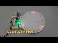 How to Make LED Rotation Using NE555 IC & CD4017 IC
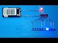 10 step LEDs charser using ic 4017 only without PCB board
 How to Make a LED Cube at Home
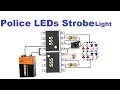 LED Police Lights & Sirens | Warning Strobe Light
 LED Chaser Circuit with 555 timer ic
 How To Make a Police Strobe light
 How PCB is Made in China - PCBWay - Factory Tour
 Top 5 useful electronics projects use ne555 timer ic, diy projects
 Top 3 Simple LED Flasher Circuits
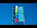 LEDs charser using transistors without PCB , Electronic project