DIY IGBT Motor Controller
Upgrade from my first video: http://www.youtube.com/watch?v=iU0KLyCgTHk
Again a 1 quadrant PWM motor controller, made from IGBTs instead of MOSFETs. Also, the upgraded motor - both for my go-kart project.
See my blog at will-ev.blogspot.com
For people asking for schematics - for now I won't provide one, maybe when I have time.
It's really simple. Two "single" IGBTs - one used as a switch, which connects Motor- to Battery-; the other as a freewheeling diode from Motor+ to Motor-.
An IGBT snubber (blue) across the switching IGBT - just a ~0.6uF 600V cap, there are more complicated ones but you have to choose those more carefully.
A capacitor bank across Battery+ and Battery- made with electrolytics (~30mF) and polypropylene (~5uF) and one $12 MLC ceramic cap (designed for switching power supply). Get yourself an IGBT driver, but I used a MOSFET driver instead - takes 5V PWM from microcontroller and outputs huge currents to quickly charge/discharge the IGBT 0 to 15V. (really should be -5 to 15V but I was lazy)
All the high current paths must be low inductance. Notice the amount of copper I used!
Oh, lastly connect Motor+ to Battery+ to complete the circuit. So, when IGBT is ON, current flows B+ to M+, through motor to M-, through switching IGBT to B-. When IGBT is off, the current flows from M- through freewheeling diode to M+. As in, it continues to flow through the motor in its original direction through the motor from M+ to M- because of its inductance (and possibly because it's generating too).
Use this thread for learning: http://ecomodder.com/forum/showthread.php/paul-sabrinas-cheap-diy-144v-motor-controller-6404.html#post78198
Видео DIY IGBT Motor Controller канала electrowizard2000
Показать
Комментарии отсутствуют
Информация о видео
Другие видео канала
 Electronic Basics #28: IGBT and when to use them
 ac motor control # 3 the circuit and how to test igbts the easy way
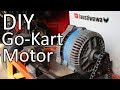 Converting a Car Alternator into a Go Kart Motor
 Go Kart - Test Drive
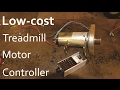 Low Cost DC Motor Controller For Treadmill
 cómo realizar control de velocidad motor DC con módulo IGBT
 Variable Frequency Drives Explained - VFD Basics IGBT inverter
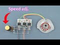 How to make BLDC motor ESC using mosfet
 CALENTADOR DE INDUCCION CON UNA SOLDADORA INVERTER SIN MODIFICAR NADA, FACIL Y RAPIDO Recalibrando
 Very Simple High Power 7000W Induction Heater 12v DC Building a Powerful Induction Heater
 cómo probar un módulo IGBT
 Power Inverters Explained - How do they work working principle IGBT
 Building an Electric Car - EV Parts - Building an open source inverter logic board - Nissan Leaf
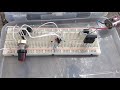 práctica no.3 IGBT control de velocidad de motor
 12V 60A DC from 220V AC for High Current DC Motor 1000W - Amazing idea
 MOSFET BJT or IGBT - Brief comparison Basic components #004
 Building a 1.4kW Induction Heater
 #243 Troubleshooting Flextronics Control Board for Automatic Washing Machines
 How to Diagnose a Shorted Motor Controller
 Controlador PWM para motores de corriente alterna monofásica