- Популярные видео
- Авто
- Видео-блоги
- ДТП, аварии
- Для маленьких
- Еда, напитки
- Животные
- Закон и право
- Знаменитости
- Игры
- Искусство
- Комедии
- Красота, мода
- Кулинария, рецепты
- Люди
- Мото
- Музыка
- Мультфильмы
- Наука, технологии
- Новости
- Образование
- Политика
- Праздники
- Приколы
- Природа
- Происшествия
- Путешествия
- Развлечения
- Ржач
- Семья
- Сериалы
- Спорт
- Стиль жизни
- ТВ передачи
- Танцы
- Технологии
- Товары
- Ужасы
- Фильмы
- Шоу-бизнес
- Юмор
🔋 How Push-Pull Transistor Circuit Works ⚡ | Animation for Beginners 🎓 | #ElectronicsShorts
Welcome to this short video about the Push-Pull Transistor Circuit, a simple and effective way to amplify electrical signals using two transistors working together. 💡
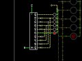
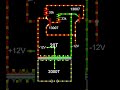
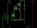
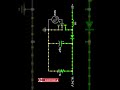
This animation clearly shows how a push-pull circuit operates with one NPN transistor and one PNP transistor, connected in a complementary way. It is one of the most common amplifier configurations used in electronics.
⚙️ How It Works
When the input signal is positive, the NPN transistor conducts and pushes current through the load.
When the input signal is negative, the PNP transistor conducts and pulls current back.
This alternating action of “pushing” and “pulling” creates a smooth alternating output signal.
That’s why it’s called a Push-Pull circuit — because the current is alternately pushed and pulled through the load! ⚡
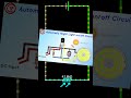
🔧 Main Components Used
NPN Transistor
PNP Transistor
Load (Speaker or LED)
Input signal source
Power supply
🧠 Applications of Push-Pull Circuit
Push-pull circuits are widely used in:
Audio amplifiers 🎵
Class B and Class AB amplifiers
Signal drivers
DC-AC converters
Low distortion output stages
Because both transistors share the work, power efficiency is high and heat is reduced — a key advantage over single-transistor amplifiers.
🎓 Educational Importance (O/L & A/L ICT / Tech)
Learning about push-pull circuits helps students understand:
How transistor pairs work in opposite phases
How AC signals are amplified
How power amplifiers are designed
The importance of reducing distortion in electronic outputs
This circuit is an essential concept in basic electronics and practical amplifier design.
If you found this video helpful, please:
✅ Like 👍 the video
✅ Share 🔁 with friends
✅ Subscribe 🔔 for more simple electronics animations and tutorials!
#PushPullCircuit #Electronics #TransistorAmplifier #ElectronicsAnimation #AmplifierBasics #ElectronicsTutorial #OLelectronics #ALtechnology #ICTtutorial #PushPullAmplifier #SimpleElectronics #TransistorCircuit #ElectronicsProject #Shorts
Qulity photos download කරන්න here: https://500px.com/p/priyashansuchinthaka
Видео 🔋 How Push-Pull Transistor Circuit Works ⚡ | Animation for Beginners 🎓 | #ElectronicsShorts канала SP-ThinkHub
This animation clearly shows how a push-pull circuit operates with one NPN transistor and one PNP transistor, connected in a complementary way. It is one of the most common amplifier configurations used in electronics.
⚙️ How It Works
When the input signal is positive, the NPN transistor conducts and pushes current through the load.
When the input signal is negative, the PNP transistor conducts and pulls current back.
This alternating action of “pushing” and “pulling” creates a smooth alternating output signal.
That’s why it’s called a Push-Pull circuit — because the current is alternately pushed and pulled through the load! ⚡
🔧 Main Components Used
NPN Transistor
PNP Transistor
Load (Speaker or LED)
Input signal source
Power supply
🧠 Applications of Push-Pull Circuit
Push-pull circuits are widely used in:
Audio amplifiers 🎵
Class B and Class AB amplifiers
Signal drivers
DC-AC converters
Low distortion output stages
Because both transistors share the work, power efficiency is high and heat is reduced — a key advantage over single-transistor amplifiers.
🎓 Educational Importance (O/L & A/L ICT / Tech)
Learning about push-pull circuits helps students understand:
How transistor pairs work in opposite phases
How AC signals are amplified
How power amplifiers are designed
The importance of reducing distortion in electronic outputs
This circuit is an essential concept in basic electronics and practical amplifier design.
If you found this video helpful, please:
✅ Like 👍 the video
✅ Share 🔁 with friends
✅ Subscribe 🔔 for more simple electronics animations and tutorials!
#PushPullCircuit #Electronics #TransistorAmplifier #ElectronicsAnimation #AmplifierBasics #ElectronicsTutorial #OLelectronics #ALtechnology #ICTtutorial #PushPullAmplifier #SimpleElectronics #TransistorCircuit #ElectronicsProject #Shorts
Qulity photos download කරන්න here: https://500px.com/p/priyashansuchinthaka
Видео 🔋 How Push-Pull Transistor Circuit Works ⚡ | Animation for Beginners 🎓 | #ElectronicsShorts канала SP-ThinkHub
push pull circuit push pull amplifier push pull transistor amplifier basics push pull working push pull circuit animation npn pnp transistor class b amplifier class ab amplifier transistor pair circuit simple electronics tutorial a/l technology ict electronics electronics for beginners transistor animation transistor circuit explanation power amplifier push pull configuration electronics education amplifier working electronics short transistor basics
Комментарии отсутствуют
Информация о видео
14 октября 2025 г. 8:45:01
00:01:03
Другие видео канала